TURNKEY C&I ENERGY STORAGE SOLUTION BRIEF: DEPLOYING RAPID INTERCONNECTION SAFETY
EXECUTIVE SUMMARY
This document provides a comprehensive technical overview of the Quick Disconnect Terminal (QDT) series, a critical safety and operational interface for commercial and industrial (C&I) energy storage systems (ESS). Designed for utility-scale and distributed storage assets, the QDT ensures rapid, reliable, and safe electrical isolation during maintenance, emergency shutdown, and system reconfiguration. Engineered to the highest standards of durability and fail-safe operation, the QDT series is integral to Sungrow’s commitment to system-level safety, asset protection, and operational uptime. This datasheet details the hardware architecture, performance specifications, and compliance certifications that position the QDT as the industry benchmark for interconnection safety.
SYSTEM ARCHITECTURE & SAFETY PROTOCOLS
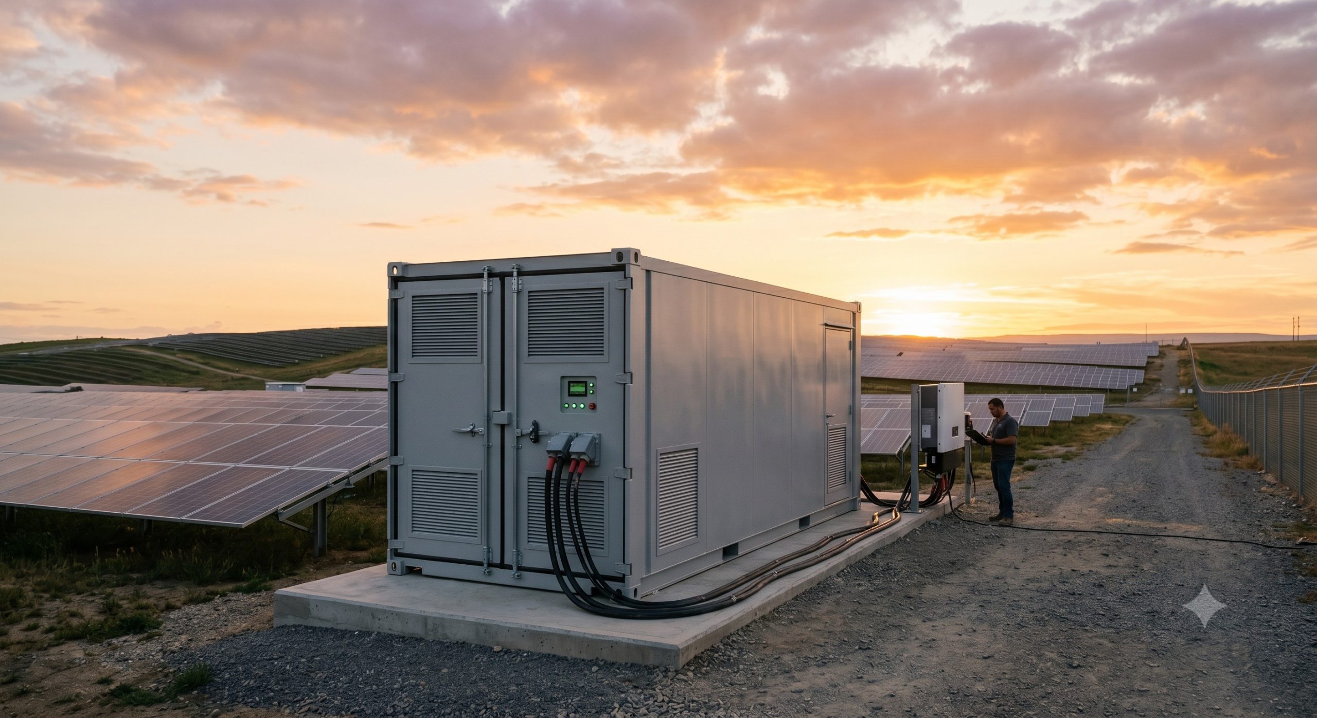
The Quick Disconnect Terminal is a manually operated, load-break rated disconnect switch that provides a visible air gap in the DC or AC circuit path. It is strategically positioned between the battery energy storage unit and the power conversion system (PCS) or between the PCS and the grid/load interface. The architecture incorporates a robust, spring-assisted mechanism that guarantees rapid contact separation, effectively extinguishing any electrical arc and ensuring safe isolation even under fault conditions. The terminal is housed in an IP66-rated, UV-stabilized enclosure, suitable for outdoor pad-mounted or indoor rack installations.
KEY FEATURES
– Rapid Disconnection & Load-Break Capability: The QDT is rated for full load-break disconnection, enabling safe isolation of the ESS from the PCS or grid within milliseconds. This feature is critical for emergency stop (E-Stop) functionality and for safeguarding personnel during maintenance procedures.
– Visible Contact Confirmation: A mechanical indicator provides a clear, visible confirmation of the switch position (ON/OFF), eliminating ambiguity and ensuring that the circuit is physically de-energized before access is permitted. This is a fundamental requirement for lockout/tagout (LOTO) safety protocols.
– Robust Arc Extinguishing: The QDT utilizes advanced arc chutes and blow-out coils to rapidly quench the electrical arc generated during load disconnection. This prolongs contact life, reduces maintenance frequency, and ensures reliable operation over thousands of switching cycles.
– Fail-Safe Mechanism: The switch mechanism is designed with a spring-return action to the OFF position in the event of a mechanical failure, ensuring a default-to-safe state. This failsafe architecture is paramount for preventing hazardous scenarios.
– Versatile Application: Available in both DC and AC configurations, the QDT series is compatible with a wide range of system voltages and currents, making it suitable for diverse C&I and utility-scale ESS topologies, including PV-storage-charging infrastructure.
COMPLIANCE & STANDARDS
– UL 98B – Enclosed and Dead-Front Switches
– UL 508 – Industrial Control Equipment
– IEC 60947-3 – Low-voltage switchgear and controlgear: Switches, disconnectors, switch-disconnectors and fuse-combination units
– IEC 61439 – Low-voltage switchgear and controlgear assemblies
– NEMA 3R / IP66 – Enclosure rating for outdoor use
– RoHS & REACH – Environmental compliance
TECHNICAL SPECIFICATIONS
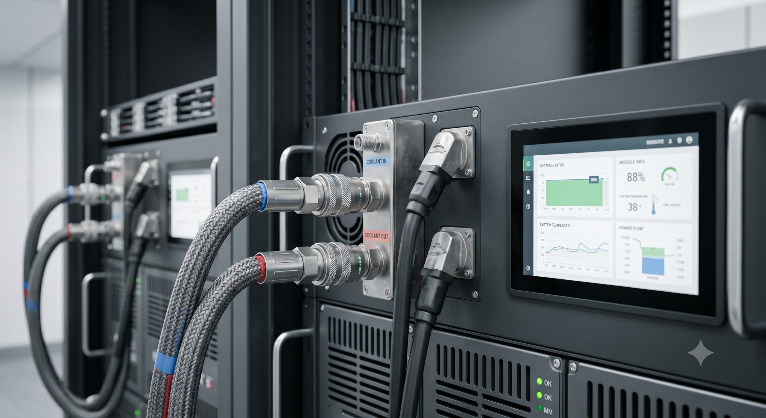
The following parameters define the standard performance metrics of the QDT series. Specifications may vary based on model and application; please consult the factory for custom configurations.
| Parameter | Specification |
|---|---|
| Nominal Voltage (DC) | Up to 1500 V DC |
| Nominal Voltage (AC) | Up to 690 V AC |
| Rated Operational Current (Ie) | 200 A to 1600 A (Model Dependent) |
| Rated Short-Circuit Withstand (Icw) | 50 kA for 1s |
| Mechanical Endurance | > 10,000 operations |
| Electrical Endurance | > 1,000 operations at rated load |
| Enclosure Rating | IP66 / NEMA 3R |
| Operating Temperature | -25°C to +55°C |
| Storage Temperature | -40°C to +70°C |
| Mounting | Flange or DIN Rail |
| Terminals | Copper busbar or cable lugs |
| Pollution Degree | 3 |
INDUSTRIAL DEPLOYMENT
The QDT is a cornerstone of safe and maintainable ESS installations. Its deployment is recommended in all grid-connected and island-mode systems, particularly in locations requiring high availability and strict adherence to safety regulations. Typical applications include:
– Commercial & Industrial Peak Shaving: Provides a secure isolation point for scheduled maintenance without interrupting the main facility power, ensuring high system uptime.
– Micro-Grid Infrastructure: Enables rapid islanding and reconnection of storage assets, ensuring grid stability and safe transition between grid-connected and off-grid modes.
– PV-Storage-Charging Stations: Facilitates safe installation and servicing of the storage component within a complex hybrid power system, protecting personnel working on the DC bus.
– Emergency Response: Offers a clear and accessible point of disconnection for fire services or emergency personnel, enabling rapid de-energization of the entire storage system during critical incidents.
For detailed installation guidelines, wiring diagrams, and specific model selection, please consult the QDT Installation & Operation Manual or contact our technical support team.
📥 Download Technical Specification
Click the button below to view or download the full official PDF datasheet.