COMMERCIAL HIGHLIGHTS
The Home microgrid integration setup manual represents a comprehensive engineering framework for deploying residential-scale battery energy storage systems (BESS) within a unified microgrid architecture. This application note serves as a definitive reference for system integrators, EPC contractors, and technical decision-makers seeking to implement resilient, grid-interactive home microgrid solutions with Tier-1 LFP battery technology.
STRUCTURAL CHASSIS OVERVIEW
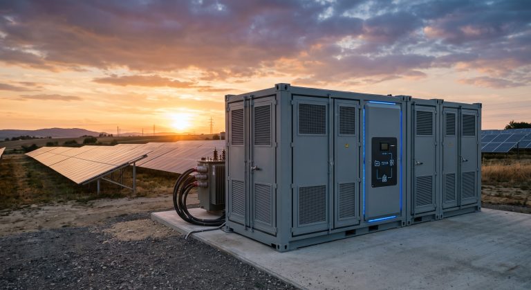
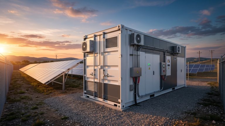
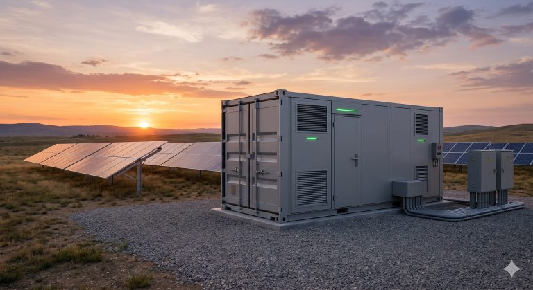
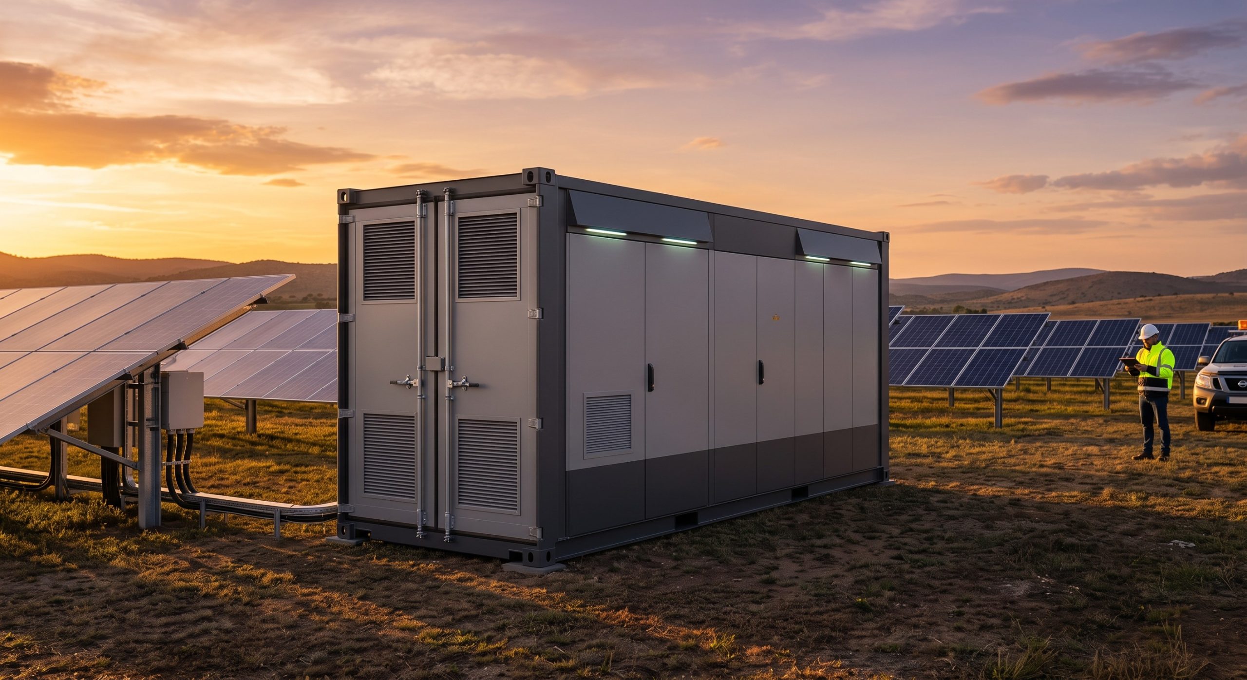
The home microgrid integration platform is engineered around a modular, wall-mountable or floor-standing enclosure designed for indoor and outdoor residential installations. The chassis accommodates a high-density lithium iron phosphate (LFP) cell stack, a bi-directional power conversion system (PCS), and an intelligent energy management system (EMS) within a single integrated unit. The enclosure is constructed from corrosion-resistant galvanized steel with an IP65 protection rating, ensuring durability across diverse climatic conditions. Cable entry points are strategically positioned at the base and rear to facilitate clean conduit routing and minimize electromagnetic interference. The structural design prioritizes ease of installation, with front-access service panels enabling rapid maintenance without disrupting adjacent units.
SUPPORTED VOLTAGES
The Home microgrid integration setup manual specifies compatibility with a wide range of grid and load voltages to accommodate global residential standards. The system supports nominal AC grid voltages of 120 V, 230 V, and 240 V (single-phase) as well as 400 V (three-phase) configurations. The DC bus operates at a nominal 400 V to 800 V range, depending on the selected battery module configuration. The integrated PCS enables seamless bi-directional power flow, supporting grid-tied, off-grid, and hybrid operating modes. The system is designed for automatic voltage and frequency ride-through, ensuring stable operation during grid fluctuations and enabling uninterrupted power supply to critical home loads.
PERFORMANCE SPECS
The Home microgrid integration setup manual outlines peak performance metrics that underscore the platform’s suitability for residential peak shaving, self-consumption optimization, and backup power applications. The system achieves a round-trip efficiency of up to 96% under standard operating conditions. The PCS delivers a continuous AC output power ranging from 5 kW to 15 kW, with a peak surge capability of 200% for 10 seconds to support motor loads such as HVAC compressors and well pumps. The battery modules utilize Tier-1 LFP cells with a cycle life exceeding 6,000 cycles at 80% depth of discharge (DoD). The integrated EMS supports time-of-use (TOU) arbitrage, demand response, and photovoltaic (PV) self-consumption maximization through advanced forecasting algorithms.
| Parameter | Specification |
|---|---|
| Nominal Capacity | 10 kWh / 20 kWh per cabinet |
| Cooling Method | Smart Liquid Cooling |
| Cell Chemistry | Tier-1 LFP |
| Round-Trip Efficiency | Up to 96% |
| AC Output Power | 5 kW – 15 kW (continuous) |
| Peak Surge Capability | 200% for 10 seconds |
| Cycle Life | >6,000 cycles at 80% DoD |
| Protection Rating | IP65 |
| Operating Temperature | -10°C to +50°C |
| Certifications | UL 9540, UL 9540A, IEC 62619, CE |
| Grid Compliance | IEEE 1547, UL 1741 SA, VDE-AR-N 4105 |
| Communication | RS-485, CAN, Wi-Fi/Ethernet |
CERTIFICATIONS MATRIX
The Home microgrid integration setup manual complies with the most stringent international safety and performance standards. The platform holds UL 9540 certification for energy storage systems and UL 9540A validation for thermal runaway fire propagation resistance. Additionally, the system meets IEC 62619 requirements for industrial battery safety, IEC 62109 for power conversion equipment, and CE marking for European market access. Grid interconnection compliance includes IEEE 1547 and UL 1741 SA for North America, as well as VDE-AR-N 4105 and EN 50549 for European grid codes. The integrated fire suppression module is certified to NFPA 855 standards, ensuring residential-grade safety.
GRID SCHEMATIC
The grid schematic for the Home microgrid integration setup manual illustrates the electrical topology of a typical residential deployment. The system is configured as a parallel AC-coupled architecture, with the BESS connected at the main distribution panel. A dedicated energy meter provides real-time consumption and generation data to the EMS, which orchestrates power flow between the PV array, battery, grid, and home loads. The schematic includes provisions for a critical load sub-panel, enabling seamless islanding during grid outages. The bi-directional PCS interfaces with the grid through a dedicated circuit breaker and surge protection device, ensuring code-compliant installation. Communication pathways include RS-485, CAN bus, and Wi-Fi/Ethernet for cloud-based monitoring and remote firmware updates.
📥 Download Technical Specification
Click the button below to view or download the full official PDF datasheet.