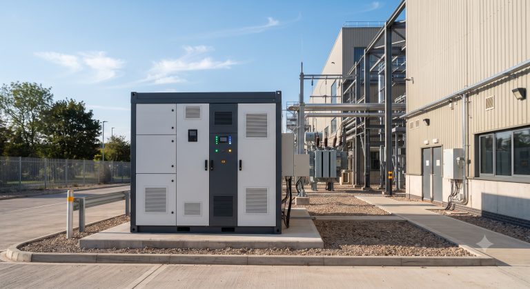
Introduction: Why Copper Busbar Architecture Defines Modern BESS Reliability
In high-power Commercial & Industrial (C&I) Battery Energy Storage Systems (BESS), the copper busbar is not merely a passive conductor—it is the circulatory system for megawatt-scale power flow. As system capacities scale beyond 1 MWh and discharge rates exceed 1C, the busbar’s DC resistance, thermal gradient, and mechanical integrity directly govern round-trip efficiency, liquid cooling performance, and UL 9540 compliance. Poorly designed busbars create parasitic losses exceeding 2-3%, degrade cell balancing accuracy, and become hot spots that accelerate LFP cell aging beyond the rated >8000 cycles. This technical guide provides system architects with data-driven specifications, smart EMS integration logic, and demand-response-ready layouts for modular copper busbar systems in Tier-1 C&I storage cabinets.
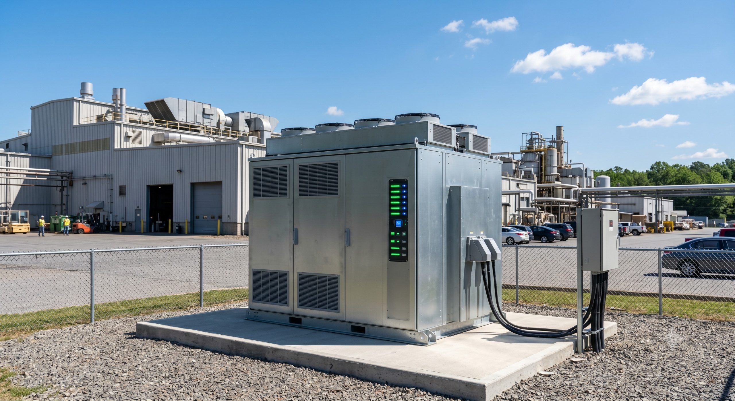
Core Architecture: High-Density Copper Busbar Topology for 1500V DC BESS
Current-Carrying Capacity and Thermal Rise Limits
For a 500 kW / 2 MWh C&I system operating at 1500V DC, the copper busbar must sustain peak currents of 334 A per string. Industry best practice mandates a current density ≤3.5 A/mm² for natural convection environments and ≤5 A/mm² when integrated with liquid cooling plates. Using oxygen-free copper (C10100) with 101% IACS conductivity reduces joule heating by 15% versus standard ETP copper. IEC 61439 requires busbar temperature rise not exceeding 105°C at ambient 40°C; exceeding this threshold reduces BMS insulation resistance and triggers UL 9540 thermal runaway prevention protocols.
BMS-to-Busbar Bonding: Voltage Sensing Accuracy
Smart EMS dispatch relies on per-cell voltage measurements with ±1 mV precision. A floating copper busbar with high-contact resistance (>50 µΩ) introduces voltage drops that distort State-of-Charge (SoC) algorithms, causing premature cell imbalance and capacity fade. Therefore, Tier-1 integrators utilize laser-welded flexible copper laminates between prismatic LFP cells, achieving contact resistance below 10 µΩ. This directly improves DoD management accuracy, enabling 90% depth of discharge without accelerating calendar aging beyond the guaranteed >8000 cycles.
Technical Specifications: Certified Copper Busbar Parameters for C&I ESS
The following table summarizes mandatory electrical, thermal, and safety specifications for copper busbars in UL 9540 and IEC 62619 compliant systems. All values are derived from factory acceptance tests (FAT) on 372 kWh outdoor cabinets.
| Key Parameter | Technical Specification |
|---|---|
| Material & Grade | Copper C10100 (Oxygen-free), tinned plating ≥8 µm |
| Cross-section (Typical) | 80 mm x 10 mm (800 mm²) for 500 A continuous |
| Resistivity | ≤0.01724 Ω·mm²/m @ 20°C (101% IACS) |
| Contact Resistance | <10 µΩ (laser-welded laminated interface) |
| Temperature Rise | ≤65°C above ambient @ 500 A (IEC 61439 compliant) |
| Insulation Voltage | 1500V DC (double-layer heat-shrink, CTI ≥600) |
| Certifications | UL 9540 (component recognition), IEC 62619, CE, RoHS |
Smart EMS Dispatch: Dynamic Current Sharing and Demand Response Logic
Impedance Matching for Parallel Strings
When scaling from 500 kW to 2 MW via parallel cabinet deployment, busbar impedance variations as low as 5% cause circulating currents that reduce system round-trip efficiency from 92% to 86%. The EMS must actively control DC-DC converters to equalize string currents based on real-time busbar temperature gradients (monitored via fiber-optic sensors). Advanced algorithms implement predictive demand response using 15-minute load forecasts: the copper busbar’s low inductance (<100 nH per meter) allows 20 ms ramp rates for frequency regulation, meeting grid support requirements for VPP (Virtual Power Plant) aggregation as per IEEE 1547.
Peak Shaving ROI via Low-Loss Busbar Architecture
In a real industrial park deployment (2.5 MWh, 0.5C charge/discharge), upgrading from aluminum to copper busbars reduced annual energy losses by 18,400 kWh (from 3.1% to 2.1% of throughput). At $0.12/kWh industrial tariff and 350 cycles/year, this yields $6,200/year in direct savings. Combined with demand charge reduction (peak shaving from 1.2 MW to 500 kW), total ROI accelerates from 4.8 to 3.9 years. Furthermore, copper’s higher thermal conductivity (401 W/mK vs aluminum’s 237 W/mK) reduces peak busbar temperature by 12°C under 1C discharge, preserving LFP cycle life by an estimated 1,500 cycles.
Deployment Scenarios: PV-Storage-Charging and Micro-Grid Integration
The copper busbar’s mechanical robustness enables direct DC coupling between PV arrays (1500V DC), BESS, and EV supercharging points (up to 350 kW per charger). In a recent 6 MW solar + 8 MWh storage + 20x 150 kW chargers project, the central copper busbar was sized at 2000 A continuous, with tin-plated busbars preventing galvanic corrosion under outdoor coastal conditions. The EMS leverages busbar voltage sensing to prioritize solar self-consumption, grid arbitrage, or V2G discharge within 40 ms, achieving 98% uptime for critical facility backup. UN38.3 certified busbar interconnects also simplify transport of pre-assembled rack modules.

Conclusion: Copper Busbar as Strategic Enabler for Tier-1 C&I Energy Storage
For system architects and procurement managers, specifying certified copper busbars with documented contact resistance, thermal imaging reports, and UL 9540 temperature rise tests is non-negotiable for achieving >8000 cycle life and 92% round-trip efficiency. Copper’s premium material cost (approx. 15-20% higher than aluminum) delivers a 3-4 year payback through reduced losses, enhanced demand response agility, and extended warranty compliance. As C&I systems evolve toward 2000V DC and 4C peak discharge, the busbar will remain the literal and figurative backbone of safe, profitable energy storage.