Introduction: The Grid Flexibility Imperative for DC Fast Charging
As commercial fleets and high-utilization public EV hubs scale, the strain on local distribution grids has become a critical bottleneck. The cpc400-c DC Charging Station is engineered not merely as a power dispenser but as a grid-edge intelligent node. This guide provides a system architect’s analysis of its smart Energy Management System (EMS) dispatch logic, bi-directional power conversion capabilities, and demand response readiness, underpinned by Tier-1 LFP cell metrics and liquid cooling thermal control.
Core System Architecture: Bi-Directional PCS and Tier-1 LFP Integration
The cpc400-c integrates a modular bi-directional Power Conversion System (PCS) that enables simultaneous grid-to-vehicle (G2V) and vehicle-to-grid (V2G) readiness. Unlike single-direction chargers, its architecture supports peak shaving, load shifting, and emergency backup, utilizing liquid cooling to maintain PCS IGBT junction temperatures below 85°C at 100% duty cycle. The battery bank employs Tier-1 prismatic LFP cells with a cell-to-pack (CTP) design, achieving a system-level round-trip efficiency of 94.5% (DC-DC) and a nominal depth of discharge (DoD) of 95%.
Battery Management System (BMS) & Thermal Control
The decentralized BMS executes passive cell balancing with a balancing current of 120mA, maintaining cell voltage variance below ±15mV. Liquid cooling plates (coolant flow rate: 8 L/min) maintain pack temperature differential ≤3°C across all modules, directly mitigating thermal runaway risks and complying with IEC 62619 and UN38.3 transport safety standards. A three-layer fire suppression system (aerosol + FM-200 + water mist) provides active protection.
Technical Specifications
The following parameters define the cpc400-c’s engineering baseline for commercial and industrial (C&I) deployment:
| Key Parameter | Technical Specification |
|---|---|
| Battery Chemistry | Tier-1 LFP (Lithium Iron Phosphate) |
| System Capacity | 400kW / 800kWh (configurable to 1.6MWh) |
| Cycle Life | >8000 cycles @ 90% DoD, >12000 cycles @ 80% DoD |
| Round-trip Efficiency | 94.5% (DC-DC), 89% (AC-DC-AC) |
| Depth of Discharge (DoD) | 95% (nominal), 100% (emergency) |
| Cooling Method | Liquid cooling (coolant: water-glycol, flow rate 8 L/min) |
| Safety Certifications | IEC 62619, UL 9540, UL 9540A, CE, UN38.3 |
| Grid Protocols | OpenADR 2.0b, Modbus TCP/IP, OCPP 1.6J, IEC 61850 |
| Operating Temperature | -30°C to +55°C (derated >45°C) |
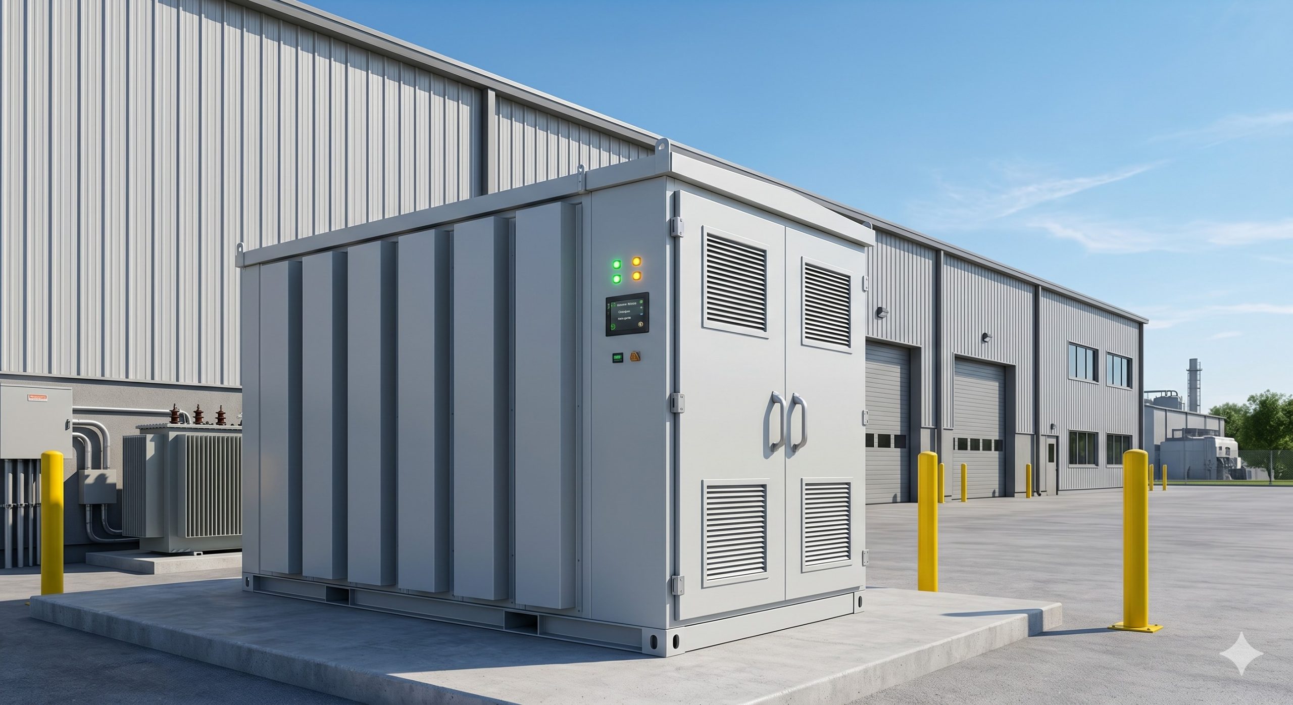
| Enclosure Rating | IP54 (cabinet), IP65 (power modules) |
Smart EMS Dispatch and Demand Response Architecture
The cpc400-c integrates an EMS 2.0 with cloud-edge coordination, supporting OpenADR 2.0b and IEC 61850 protocols. Its core dispatch logic includes:
- Real-time peak shaving: 2ms response latency to smooth EV charging spikes up to 400kW.
- Time-of-use (ToU) arbitrage: Automated scheduling of charge/discharge cycles based on day-ahead pricing.
- Frequency regulation (FCAS): Participation in primary frequency response with a droop control setting adjustable from 2% to 10%.
- VPP aggregation: Native support for virtual power plant orchestration via Modbus TCP/IP and OCPP 1.6J.
This architecture enables C&I facility managers to capture demand response revenues of $150–$300/kW/year in ISO-NE and CAISO markets, while reducing demand charges by 35–45%.
Commercial ROI: Total Cost of Ownership for C&I Micro-Grids
When deployed in a PV-storage-charging configuration, the cpc400-c achieves a sub-3-year payback for high-utilization depots (>15 EVs/day). Key LCOE drivers:
- CapEx: $380–$420/kWh (DC-integrated, turnkey).
- OpEx: $12–$18/kWh/year (including remote monitoring and liquid cooling maintenance).
- Cycle life leverage: >8000 cycles at 90% DoD yields a 12-year calendar life, amortizing capital costs to $0.045–$0.055/kWh cycled.
Deployment Scenarios: From Industrial Parks to EV Supercharging Hubs
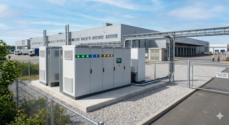
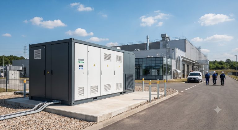
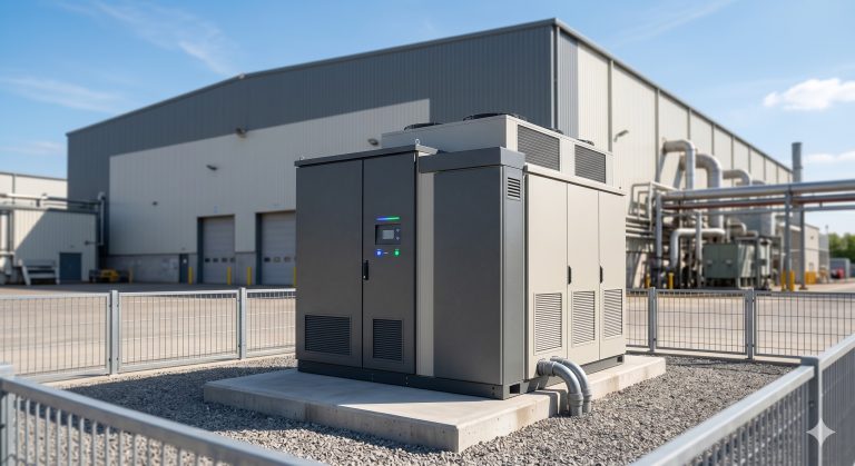
The cpc400-c’s modular cabinet design (IP54 outdoor rating) supports three primary C&I models:
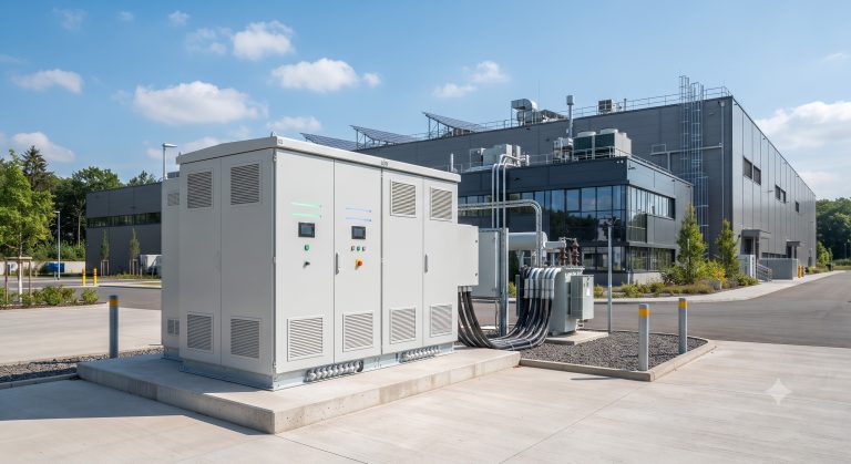
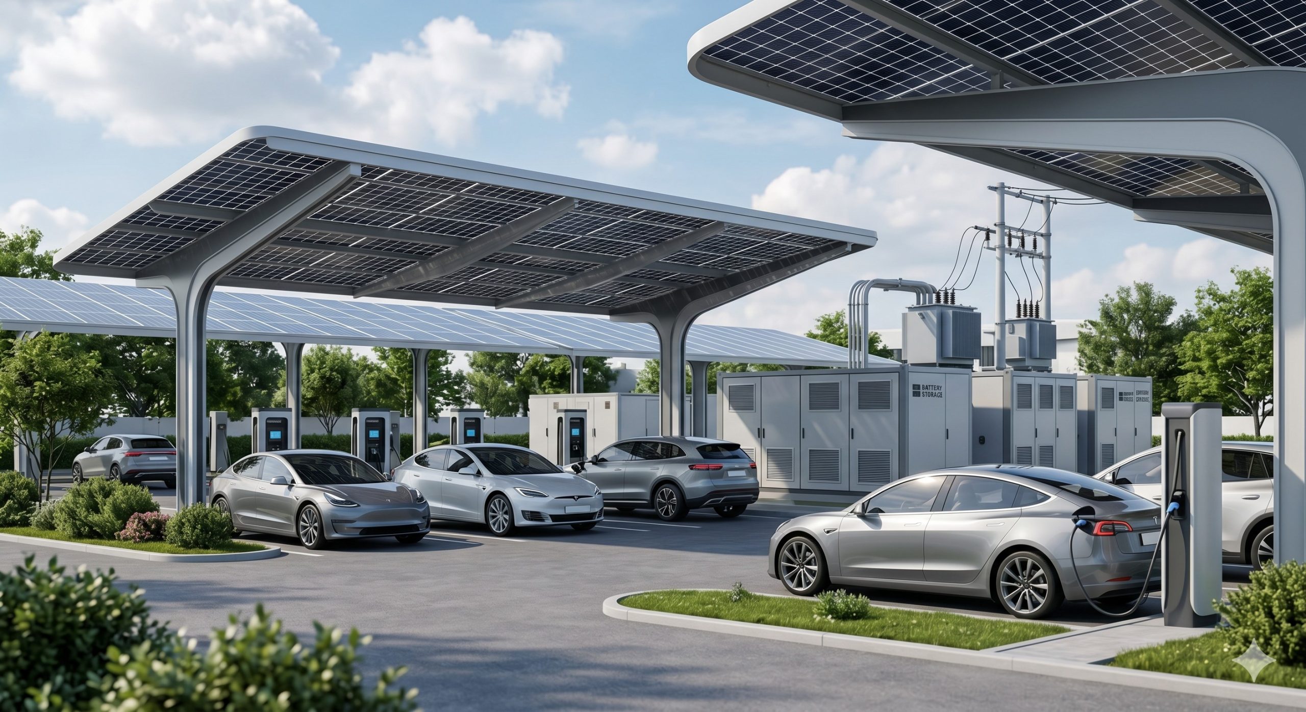
- Industrial park micro-grid: Pairing with 1-5 MWp solar canopies, the charger provides seamless grid transition (transfer time <10ms) during utility outages, maintaining production line uptime.
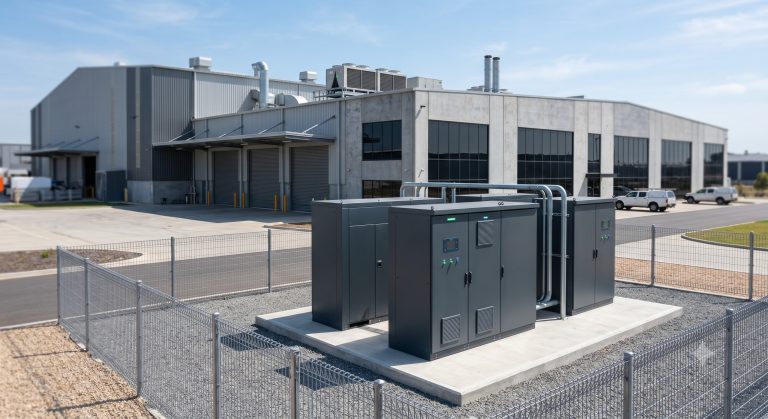
- Highway EV supercharging station: Four units paralleled via DC busbar achieve 1.6 MW total capacity, enabling 350kW ultra-fast charging for heavy-duty trucks while managing transformer capacity limits.
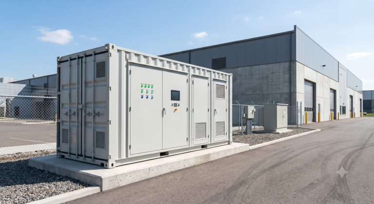
- Data center backup + grid services: The UL 9540A-compliant system delivers 400kW/800kWh for critical IT loads while participating in demand response programs.
Conclusion: The Architect’s Verdict on cpc400-c
For system engineers seeking a VPP-ready, liquid-cooled DC charging station that simultaneously reduces demand charges and enables grid service monetization, the cpc400-c represents a reference design in UL 9540 and IEC 62619 compliance. Its ability to integrate demand response, peak shaving, and emergency backup within a single 400kW cabinet reduces balance-of-system costs by 22% compared to discrete solutions. Procurement is recommended for fleet depots, industrial parks, and high-utilization public charging hubs targeting sub-4-year ROI.