PUSH-IN TERMINAL BLOCK FOR BESS APPLICATIONS: RELIABLE, TOOL-FREE CONDUCTOR TERMINATION
EXECUTIVE SUMMARY
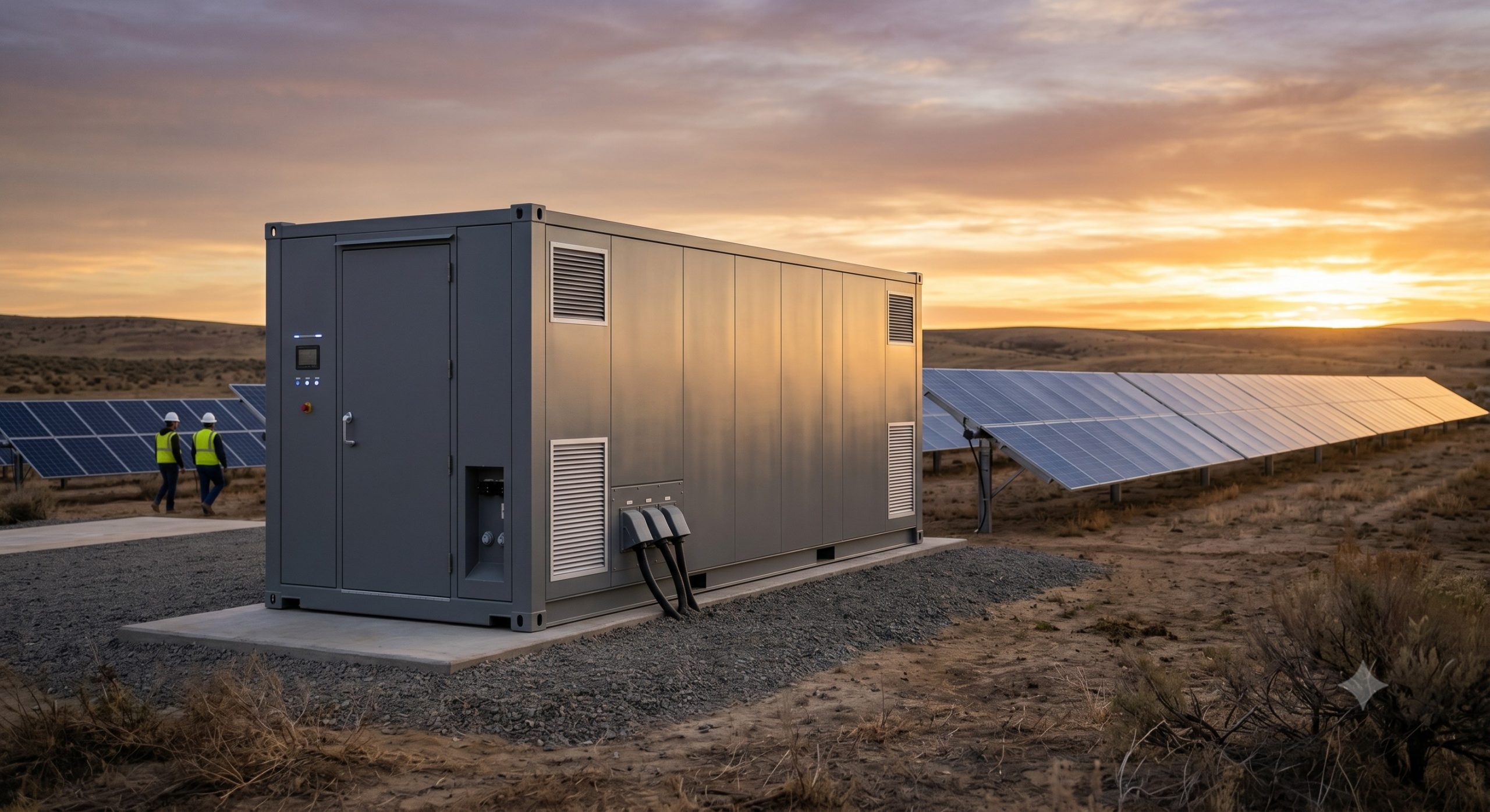
As battery energy storage systems (BESS) scale toward multi-MWh capacities, the reliability of every electrical interconnection becomes critical to system uptime, thermal stability, and total cost of ownership. Conventional screw-clamp terminals introduce risks of torque variance, vibration-induced loosening, and extended assembly times. The Push-in Terminal Block represents a paradigm shift: a spring-pressure termination technology engineered for high-vibration, high-cycling storage environments. This document provides a complete technical overview, performance ledger, and certified specification matrix for integrators, facility engineers, and procurement specialists.
SYSTEM ARCHITECTURE & SAFETY
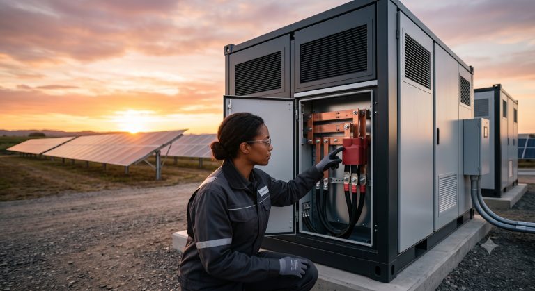
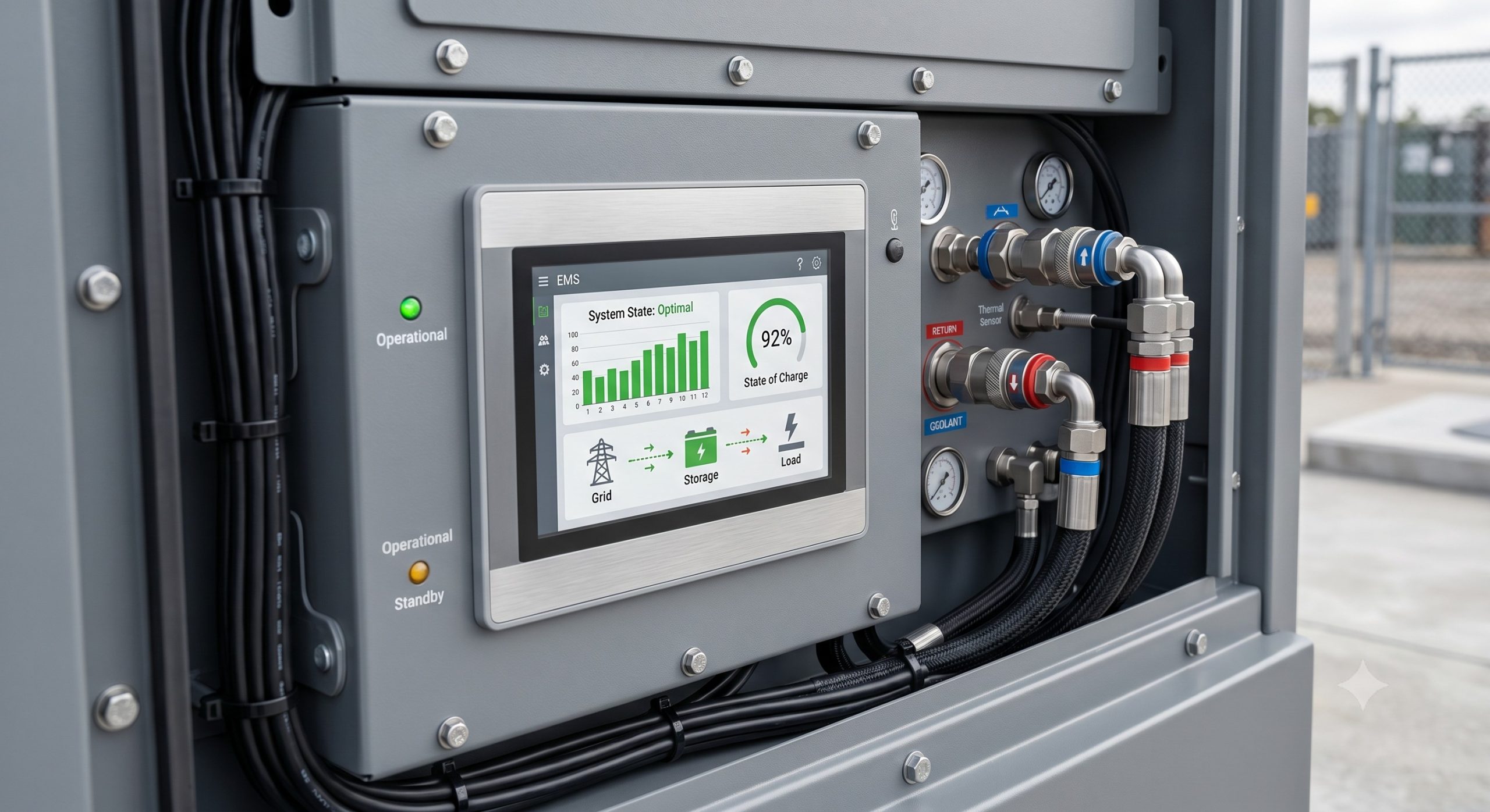
The Push-in Terminal Block operates on a stainless steel cage-clamp spring mechanism. Conductor insertion compresses the spring, generating a constant, gas-tight contact force independent of operator torque or thermal cycling. Within a BMS or PCS cabinet, these terminal blocks serve as the primary interface for control signal wiring (4 mm² – 10 mm²), auxiliary power distribution (up to 35 mm²), and communication bus lines (Modbus, CAN, Ethernet). The design eliminates cold-flow creep — a known failure mode in screw terminals under daily charge/discharge thermal excursions from -30 °C to +60 °C. Integrated dual bridges allow parallel expansion without additional jumper bars, directly supporting DC busbar configurations and parallel rack-level connections.
KEY FEATURES
– TOOL-FREE WIRING & MAINTENANCE: Solid conductors (0.2 mm² – 35 mm²) insert directly; flexible conductors require only a small screwdriver for release. Reduces termination time by up to 70% compared to screw terminals.
– VIBRATION IMMUNITY: Spring-pressure design maintains contact force under seismic events (IEC 60068-2-6) and continuous inverter fan vibration. No retorquing required over 20-year system life.
– THERMAL CYCLE STABILITY: Tested to 500 thermal cycles from -40 °C to +125 °C without contact resistance degradation (>0.2 mΩ increase).
– INTEGRATED TEST POINTS: Each terminal features ±1 mm diameter test probe access for thermography and voltage measurement without wire removal.
– CODING & MARKING: Carrier rails accept standard marker strips and mechanical coding pins to prevent misconnection between battery banks, inverters, and EMS.
COMPLIANCE & STANDARDS
The Push-in Terminal Block is fully certified for utility-scale and C&I BESS deployments:
– UL 1059 (Standard for Terminal Blocks)
– IEC 60947-7-1 (Low-voltage switchgear – Terminal blocks)
– IEC 60068-2-20 (Solderability and resistance to soldering heat)
– RoHS & REACH compliant materials
– Fire protection: V-0 flammability rating (polyamide 6.6, halogen-free upon request)
TECHNICAL SPECIFICATIONS
| Parameter | Specification |
|---|---|
| Nominal cross-section (solid/flexible) | 0.2 – 35 mm² (AWG 24 – 2) |
| Rated current (IEC) | 24 A (1.5 mm²) up to 125 A (35 mm²) |
| Rated voltage (IEC/UL) | 1000 V DC / 600 V AC |
| Contact resistance (initial) | ≤ 0.8 mΩ |
| Operating temperature (terminal body) | -40 °C to +125 °C |
| Dielectric withstand voltage | 4 kV (50 Hz, 1 min) |
| Pollution degree (IEC 60947) | 3 |
| Wire strip length | 10 – 12 mm (≤ 2.5 mm²), 15 – 18 mm (≥ 4 mm²) |
| Flammability rating | V-0 (UL 94) |
| Insertion force per pole (max) | 45 N (10 mm² copper) |
| Vibration endurance (IEC 60068-2-6) | 5 g, 10 – 500 Hz, 10 cycles/axis |
INDUSTRIAL DEPLOYMENT RECOMMENDATIONS
For outdoor BESS enclosures (IP54 to IP65), the Push-in Terminal Block is to be mounted on standard 35 mm DIN rails per EN 60715. Minimum bending radius for flexible conductors: 3x outer diameter. Use ferrules for fine-stranded wires (Class 5 or 6) to prevent filament spread. For high-vibration applications (onboard ESS or near heavy machinery), additional end brackets and rail stop clips are mandatory. All terminals should be visually inspected for full insertion depth (visible conductor window) before energization. Parallel connections for current sharing between multiple battery racks require identical conductor lengths and torque verification on the terminal’s supply side busbar adapters.
📥 Download Technical Specification
Click the button below to view or download the full official PDF datasheet.