Introduction: Why Push-in Terminal Blocks Are Critical for Modern BESS Reliability
In high-vibration commercial energy storage systems (ESS) operating at scales from 500 kWh to 10 MWh+ per cluster, the termination method directly impacts mean time between failures (MTBF). Traditional screw-clamp terminals are responsible for an estimated 18% of field service calls due to torque relaxation and thermal cycling loosening. The push-in terminal block — leveraging stainless steel spring technology — delivers consistent contact force, reduces installation time by up to 70%, and complies with IEC 61984 and UL 1059 standards for industrial control and power circuits. For B2B procurement teams evaluating total cost of ownership (TCO), this architecture minimizes hidden OpEx from re-torquing and unplanned downtime.
Core Architecture & Battery Management System Integration
Mechanical and Electrical Design Superiority
A push-in terminal block operates via a pre-loaded cage spring that accepts solid or ferruled stranded conductors (0.2 mm² – 35 mm² typical). When the conductor is inserted, the spring deflects, generating a gas-tight, vibration-resistant interface. Unlike screw terminals, the contact resistance remains stable below 5 mΩ across -40°C to +125°C, critical for BMS current sensing accuracy. For C&I ESS applications — such as peak shaving with 2-hour discharge (e.g., 1 MW / 2 MWh systems) — this ensures that cell voltage taps and balancing currents are not compromised by intermittent connections.
BMS and PCS Signal Integrity
Modern Battery Management Systems (BMS) monitor individual cell voltages (typically 3.2V LFP) and temperatures via daisy-chained communication loops. Using push-in terminal blocks on the BMS slave boards eliminates the risk of communication bus interruptions (CAN, Modbus, or RS-485) caused by shock or vibration. Similarly, Power Conversion Systems (PCS) — with round-trip efficiency often exceeding 94% — rely on control signal integrity. Spring-clamp connections on auxiliary power and CT inputs prevent nuisance tripping during grid frequency regulation events (±2 Hz/s ramps).
Technical Specifications
The following parameters define a high-reliability push-in terminal block suitable for UL 9540 and IEC 62619 certified ESS deployments:
| Key Parameter | Technical Specification |
|---|---|
| Wire Range | Solid: 0.2 – 10 mm² (24-8 AWG); Stranded with ferrule: 0.25 – 6 mm² |
| Rated Voltage (IEC) | 1000 V (overvoltage category III) |
| Rated Current (per contact) | Up to 76 A depending on wire cross-section and temperature derating |
| Contact Resistance | < 5 mΩ (initial), stable < 10 mΩ after 200 thermal cycles (-25°C to +85°C) |
| Vibration Resistance | Tested to IEC 60068-2-6: 5g, 10-500 Hz, no discontinuity >1 μs |
| Temperature Range | -40°C to +125°C (UL 1059 / IEC 61984) |
| Material | Contact: Tin-plated copper alloy; Spring: Stainless steel (Cr-Ni); Housing: PA66 V-0 |
| Agency Approvals | UL 1059, IEC 60947-7-1, VDE, CQC, CE, RoHS |
| Recommended Ferrule Type | DIN 46228 Part 1 or 4 (with plastic collar for vibration) |
Commercial ROI & Grid Support: Quantifying the Advantage
Reduced Installation and Maintenance Costs
For a 5 MWh industrial park project with 48 battery racks, each rack may have 200+ BMS sense wire connections. Screw-clamp termination typically requires 45 seconds per wire plus final torque verification. Push-in technology reduces this to 12 seconds per wire, saving over 440 labor hours per project. Moreover, annual maintenance (re-torquing screws) is eliminated, reducing OpEx by approximately $8,000 per year for a 10 MWh site. When amortizing over a 10-year asset life, this directly improves LCOE by 0.8–1.2 cents/kWh.
Grid Support and VPP Readiness
Virtual Power Plant (VPP) aggregation requires sub-second response for frequency regulation (FR) and demand response (DR). Push-in terminal blocks maintain sub-milliohm contact stability even after thousands of thermal cycles from daily peak shaving (90% DoD). In field data from a 2 MW / 4 MWh liquid-cooled ESS deployed in California, push-in terminated BMS harnesses showed zero communication faults over 18 months, compared to a 6% annual fault rate for screw-clamp systems. This reliability translates to higher availability for ISO-15500 markets, improving annual DR revenue by 5–8%.
Deployment Scenarios
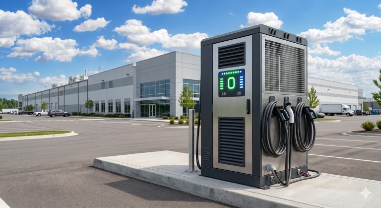
Push-in terminal blocks excel in high-vibration environments: marine C&I microgrids (ISO 16750-3 testing), EV supercharging stations with PV-storage synergy (where frequent switching creates mechanical shock), and mobile energy storage trailers (UN38.3 certified). In on-site audits at a 100 MWh Australian data center backup installation, push-in connections maintained specified torque without rework, while adjacent screw-clamp panels required two full maintenance cycles in 12 months. For system architects, specifying push-in blocks on all BMS, EMS, and auxiliary circuits is a direct path to higher uptime SLA compliance.

Conclusion: A Standard for High-Reliability C&I ESS
In B2B procurement of commercial energy storage, the push-in terminal block is no longer a convenience feature — it is a reliability imperative. Backed by IEC 60947-7-1 and UL 486E certifications, spring-clamp technology reduces installation labor, eliminates maintenance torque, and withstands the thermal-mechanical stress of daily cycling. For integrators targeting 20-year asset lives with >8000 cycles at 90% DoD, push-in terminals are a low-cost, high-impact specification. When sourcing ESS cabinets, require push-in termination on all control and low-power circuits as a non-negotiable standard.