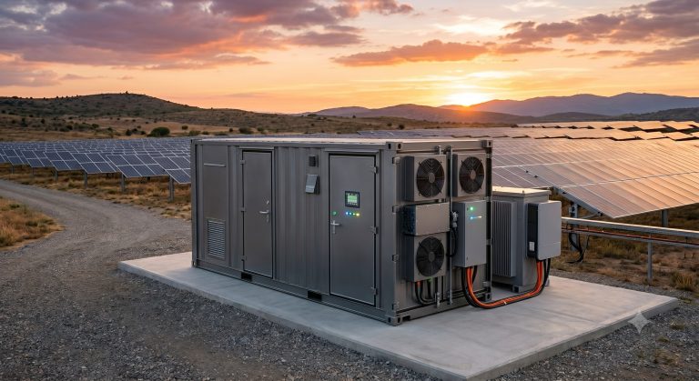
TURNKEY HARDWARE INTEGRATION & SAFETY SPECIFICATION: M6 BATTERY TERMINAL
PRODUCT IDENTIFICATION AND INTENDED USE
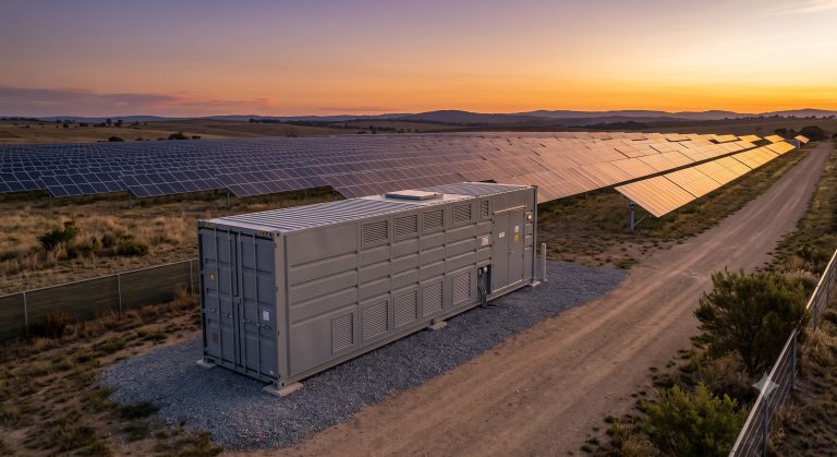
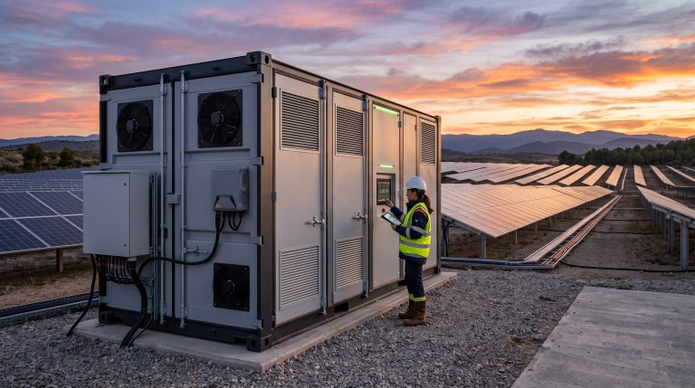
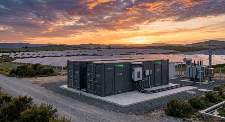
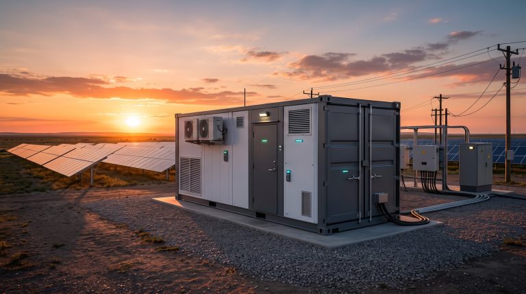
The M6 Battery Terminal represents a paradigm shift in commercial and industrial (C&I) energy storage, engineered as a compact, high-density DC-coupled storage block. This terminal is specifically designed for behind-the-meter peak shaving, demand charge management, and PV self-consumption optimization. As the foundational building block for scalable megawatt-hour systems, the M6 Terminal provides a pre-assembled, factory-tested solution that minimizes on-site engineering complexity while maximizing system safety and operational lifespan.
INTERNAL BESS TOPOLOGY AND DC BUS ARCHITECTURE
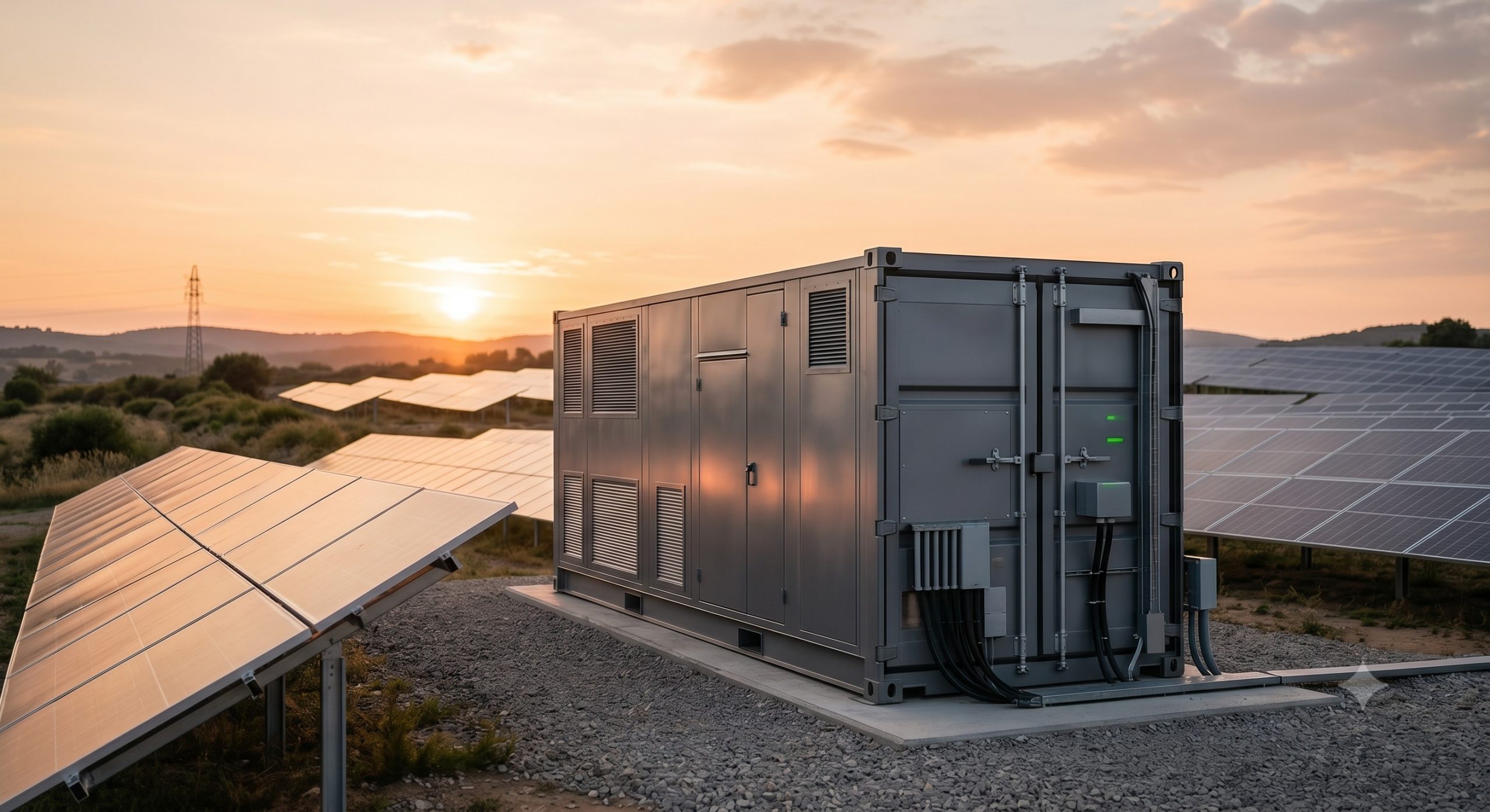
The M6 Terminal integrates a high-voltage battery array with a dedicated Battery Management System (BMS) and a localized Energy Management System (EMS) gateway. The internal topology is structured around a redundant DC busbar system capable of supporting parallel expansion configurations. Each cabinet houses modular Tier-1 LFP battery modules, connected in a series-parallel arrangement to achieve nominal DC voltages suitable for modern bi-directional PCS interfaces. The architecture prioritizes low-resistance connections to minimize thermal hotspots and ensure uniform current distribution during high C-rate charge and discharge cycles.
THERMAL PROTECTION MECHANISMS AND LIQUID COOLING PIPELINE INTERFACES
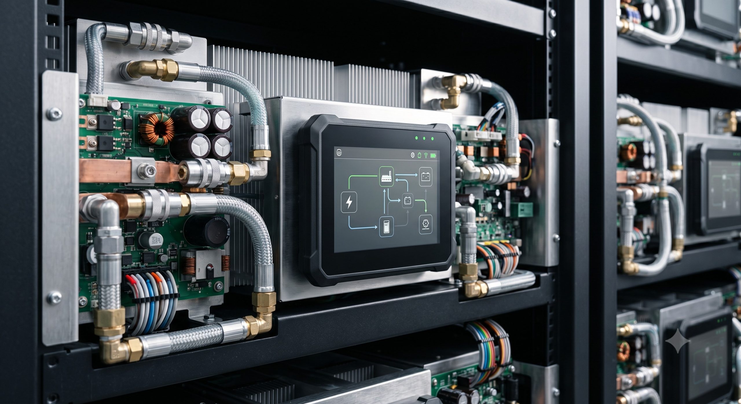
Advanced thermal management is a cornerstone of the M6 Battery Terminal design. The system utilizes a smart liquid cooling loop that interfaces with an external chiller unit or dry cooler. This closed-loop pipeline circulates a dielectric coolant through cold plates embedded within each battery module, maintaining cell temperature variance within ±2°C. This precise regulation is critical for preventing thermal runaway propagation and enhancing LFP cell cycle life. The cooling pipeline includes isolation valves, pressure sensors, and leak detection systems, allowing for safe maintenance without draining the entire fluid loop. The thermal management system is dynamically controlled by the EMS, adjusting flow rates based on real-time load demand and ambient temperature profiles.
OPERATIONAL ADVANTAGES AND GRID SUPPORT FUNCTIONS
– Peak Shaving and Demand Management: The M6 Terminal can discharge at full rated power for up to two hours, effectively shaving peak demand charges and reducing overall facility electricity costs.
– PV Self-Consumption Optimization: Integrated logic algorithms enable the system to store excess solar energy during peak generation periods and discharge it during evening peak tariffs, maximizing the ROI of solar PV investments.
– Grid Support and Micro-grid Readiness: The terminal supports frequency regulation and voltage support functions when paired with a compatible PCS. Its robust design allows for seamless islanding and reconnection to the main utility grid, making it ideal for industrial micro-grid deployments.
– Scalable Parallel Architecture: Multiple M6 Terminal units can be paralleled on a common DC bus or AC-coupled via multiple PCS units, providing a flexible pathway to scale storage capacity from 215 kWh to multiple MWh without re-engineering the core system.
SPECIFICATION MATRIX AND PERFORMANCE LEDGER
The following specification matrix details the core technical parameters of the M6 Battery Terminal. All values are verified under standard test conditions (STC) and are subject to the warranty terms detailed in the official product manual.
| Parameter | Specification |
|---|---|
| Nominal Capacity | 215 kWh |
| Nominal Voltage | 768 V DC |
| Operating Voltage Range | 648 V – 876 V DC |
| Max. Charge / Discharge Power | 100 kW / 100 kW |
| Recommended C-Rate | ≤ 0.5C (Continuous) |
| Cooling Method | Smart Liquid Cooling (Ethylene Glycol/Water) |
| Cell Chemistry | Tier-1 LFP (Lithium Iron Phosphate) |
| Round-trip Efficiency | ≥ 92% (DC side, @ 0.5C) |
| Cycle Life | ≥ 6,000 cycles @ 90% DoD, 25°C |
| Operating Temperature Range | 0°C to +45°C |
| Enclosure Rating | IP54 (Outdoor Rated) |
| Dimensions (W x D x H) | 1,200 mm x 1,350 mm x 2,400 mm |
| Weight (Approx.) | 2,800 kg |
| Certifications | UL 9540, IEC 62619, UN 38.3 |
REGULATORY COMPLIANCE AND SAFETY ACCREDITATIONS
The M6 Battery Terminal has been rigorously tested and certified to meet the most stringent international safety and performance standards. Compliance ensures seamless project permitting and eligibility for utility incentive programs. The system design incorporates multi-level active and passive protection mechanisms, including overcurrent protection, ground fault detection, and a dedicated fire suppression interface.
– UL 9540: Standard for Energy Storage Systems and Equipment. The M6 Terminal is compliant with UL 9540, covering all system-level safety requirements for battery-based energy storage systems.
– IEC 62619: Safety requirements for secondary lithium cells and batteries for use in industrial applications. The LFP cells and modules within the M6 Terminal have successfully passed the stringent test requirements of IEC 62619.
– NFPA 70 (NEC): The terminal is designed to be compliant with the National Electrical Code, including Article 706 for Energy Storage Systems.
– UN 38.3: Transport of Dangerous Goods. The battery modules have passed the UN 38.3 test requirements for safe transportation by air, sea, and land.
– Grid Code Compliance: The system is engineered to interface with standard utility grid codes, including IEEE 1547 and UL 1741 (when paired with a compliant PCS).
INDUSTRIAL DEPLOYMENT AND FACILITY LAYOUT RECOMMENDATIONS
For optimal performance and safety, the M6 Battery Terminal should be installed on a flat, level concrete pad with adequate clearance for ventilation and maintenance access. The recommended environmental conditions for operation are 0°C to 45°C ambient temperature and 5% to 95% relative humidity (non-condensing). A minimum clearance of 1.5 meters is required at the front of the cabinet for access to the EMS panel and internal components. The system is designed for outdoor deployment with an IP54 enclosure rating, ensuring protection against dust ingress and water splashing. Proper grounding and lightning protection must be incorporated into the overall facility design. The liquid cooling system requires an external heat rejection unit, which should be positioned within a 20-meter radius of the terminal to optimize coolant pipe routing and minimize pumping losses.
CONCLUSION
The M6 Battery Terminal stands as a benchmark for turnkey C&I energy storage solutions, combining high-density LFP battery technology, advanced liquid thermal management, and comprehensive safety features into a compact, easily deployable package. Its scalability, regulatory compliance, and robust performance make it an optimal asset for commercial facilities, industrial parks, and EV charging infrastructure seeking to enhance energy resilience and reduce operational costs.
📥 Download Technical Specification
Click the button below to view or download the full official PDF datasheet.