COMMERCIAL SYSTEMS ENGINEERING REFERENCE MANUAL: ENERGY MANAGEMENT SYSTEM USER MANUAL
EXECUTIVE SUMMARY
This document serves as the definitive engineering reference and operational user manual for the Energy Management System (EMS) integrated within our Tier-1 commercial Battery Energy Storage System (BESS) portfolio. Designed for system integrators, facility engineers, and asset operators, this manual details the architectural logic, control interfaces, safety protocols, and performance parameters governing the EMS. The system provides intelligent, real-time supervisory control, optimizing energy dispatch, peak shaving, demand response, and PV-storage-charging coordination while ensuring grid code compliance and maximal asset longevity. This manual consolidates hardware specifications, software functionalities, and safety compliance registers into a single authoritative reference for deployment, commissioning, and ongoing operations.

SYSTEM ARCHITECTURE & SAFETY
The EMS architecture is a three-tier, distributed control system comprising a local controller (EMS Gateway), a cloud-based supervisory platform (optional), and field-level devices (BMS, PCS, smart meters, and environmental sensors). At its core, the EMS Gateway runs a real-time Linux kernel with a deterministic 10ms control cycle. Data acquisition is performed via redundant Modbus TCP/IP and CAN 2.0B fieldbuses, with IEC 61850 GOOSE messaging for fast islanding applications. The system incorporates a multi-layer cybersecurity framework, including role-based access control, encrypted TLS 1.3 communication channels, and an integrated firewall with deep packet inspection. Safety integrity is assured through a hardware-independent watchdog timer and a fail-safe logic that triggers a controlled shutdown or grid disconnection upon communication loss or detected anomaly.
KEY FEATURES
– Feature 1: Intelligent Peak Shaving Logic: Proprietary load forecasting algorithm with a 24-hour look-ahead window, dynamically adjusting discharge depth to reduce peak demand charges by up to 30% based on site-specific utility rate structures.
– Feature 2: Seamless PV-Storage-Charging Coordination: Real-time MPPT tracking integration and EV charger load balancing, enabling up to 95% on-site renewable self-consumption while preventing transformer overload.
– Feature 3: Advanced Thermal Runaway Suppression Engine: The EMS actively monitors each LFP cell’s temperature, voltage, and internal resistance, coordinating with the liquid cooling system to maintain a ±1°C temperature differential across all cells. The system initiates a pre-alarm upon detecting deviation beyond 2°C, and an emergency shutdown in case of a critical threshold exceedance, fully compliant with UL 9540A thermal runaway propagation test requirements.
– Feature 4: Black Start & Grid-Forming Capability: The EMS supports seamless islanding and black start functionality, enabling the BESS to serve as a primary voltage and frequency reference for industrial micro-grids, restoring power within 50ms of grid failure.
– Feature 5: Cloud-Based Predictive Maintenance: Integrated diagnostic suite with 50+ parameters (e.g., cell balancing, contactor aging, coolant flow rate) that are streamed to the cloud to generate predictive alerts, reducing unplanned downtime by an estimated 25%.
COMPLIANCE & STANDARDS
The EMS and the overall BESS are meticulously designed to meet the most stringent global safety and grid interconnection standards. This includes full compliance with UL 9540 (Energy Storage Systems and Equipment), UL 1741 (Inverters, Converters, Controllers and Interconnection System Equipment for Use with Distributed Energy Resources), IEEE 1547 (Standard for Interconnection and Interoperability of Distributed Energy Resources with Associated Electric Power Systems Interfaces), and IEC 62619 (Secondary Cells and Batteries – Requirements for Safety of Lithium-Ion Cells). Additionally, the EMS supports grid protocols for CEI 0-21, VDE-AR-N 4105, and G99, ensuring turnkey integration across major international markets. The system is certified to meet the cybersecurity requirements outlined in IEC 62443-3-3 for industrial automation and control systems.
TECHNICAL SPECIFICATIONS
The EMS hardware is housed in a compact 2U rack-mountable industrial computer rated for -25°C to +65°C ambient temperature. It features a quad-core ARM Cortex-A53 processor, 4GB of ECC RAM, 32GB of industrial-grade eMMC storage, and dual redundant power supplies (24V DC / 110-230V AC). The unit supports up to 200 field I/O points and 5 concurrent communication sessions. The liquid cooling subsystem is capable of dissipating up to 15kW of thermal load while maintaining a coolant inlet temperature range of 15°C to 45°C, with a flow rate of 10-20 L/min per cabinet. The system’s A-weighted sound pressure level at 1 meter is less than 65 dBA.
| Parameter | Specification |
|---|---|
| Nominal Energy Capacity (per cabinet) | 215 kWh / 372 kWh (configurable with parallel cabinets) |
| Nominal Power (AC) | 100 kW / 200 kW (at 480V, 60Hz) |
| Cell Chemistry | Tier-1 LFP (Lithium Iron Phosphate) |
| Cooling Method | Smart Liquid Cooling (Ethylene Glycol/Water) |
| Operating Voltage Range (DC) | 600V – 900V DC (nominal 768V) |
| Round-Trip Efficiency | ≥ 92% (at 25°C, 1C charge/discharge rate) |
| EMS Communication Protocols | Modbus TCP/IP, CAN 2.0B, IEC 61850, DNP3 |
| Ambient Operating Temperature | -20°C to +50°C (derated above +45°C) |
| Ingress Protection Rating | IP54 (NEMA 3R) |
| Safety & Compliance | UL 9540, UL 1741, IEEE 1547, IEC 62619 |
| Coolant Temperature Range | +15°C to +45°C (inlet) |
| Max. Parallel Units (Scalability) | Up to 20 cabinets per cluster (7.44 MWh) |
INDUSTRIAL DEPLOYMENT
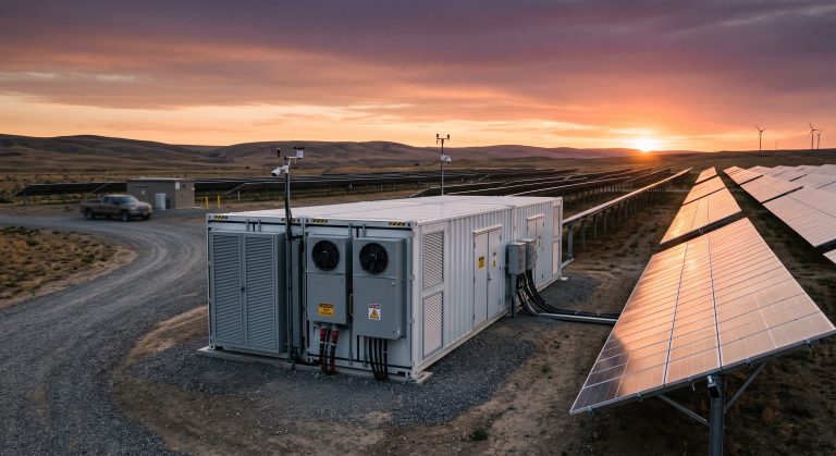
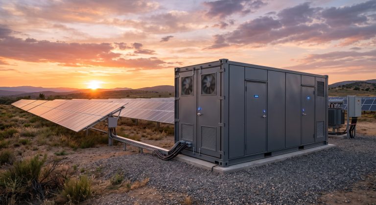
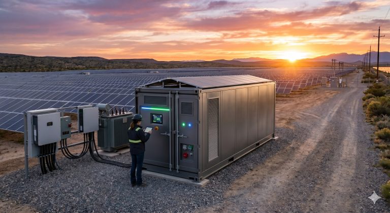
A typical deployment involves installing the EMS within the master cabinet or a dedicated climate-controlled enclosure. The site survey should ensure a stable internet connection (for cloud features) and a dedicated Ethernet network for the control LAN. The system is pre-commissioned at the factory; however, on-site parameterization is required to adjust the load profile, peak demand threshold, and grid import/export limits. We recommend the use of shielded CAT6 cables for all Ethernet connections and twisted-pair shielded cables for RS-485/MODBUS connections. The outdoor pad must be level to within ±5mm and the EMS cabinet must be secured with M12 anchor bolts. Fire suppression system integration, using an Novec 1230 or FM-200 agent, is pre-wired and configured to be triggered by the EMS upon independent detection of smoke or rapid temperature rise.

📥 Download Technical Specification
Click the button below to view or download the full official PDF datasheet.