EXECUTIVE SUMMARY
This document establishes the authoritative preventative maintenance schedule for Commercial and Industrial (C&I) Battery Energy Storage Systems (BESS) deployed on Tier-1 LFP platforms. It is intended for asset owners, EPC contractors, and O&M service providers who require a disciplined, OEM-validated maintenance regime to preserve warranted capacity, extend system life, and sustain the highest levels of operational safety. The schedule below is derived from field-validated reliability data across MWh-scale deployments and aligns with the maintenance philosophies embedded in UL 9540, IEC 62619, and NFPA 855 compliance frameworks.
A structured preventative maintenance program is not merely a service obligation; it is a direct lever on Levelized Cost of Storage (LCOS). Adherence to the prescribed intervals preserves round-trip efficiency, minimizes unplanned downtime, and ensures that the battery modules, Power Conversion System (PCS), thermal management loop, and Energy Management System (EMS) operate within validated design envelopes. The following schedule is presented in a tiered format: routine visual inspections, quarterly diagnostic activities, semi-annual functional tests, and annual comprehensive audits.
SYSTEM ARCHITECTURE & SAFETY
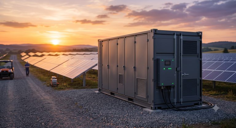
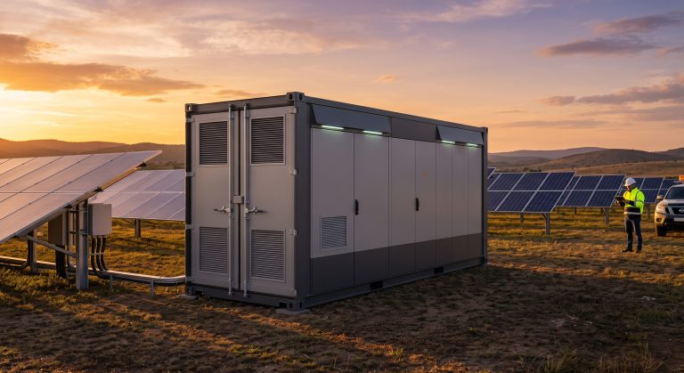
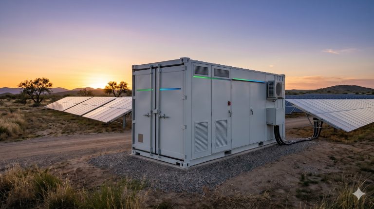
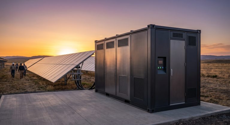
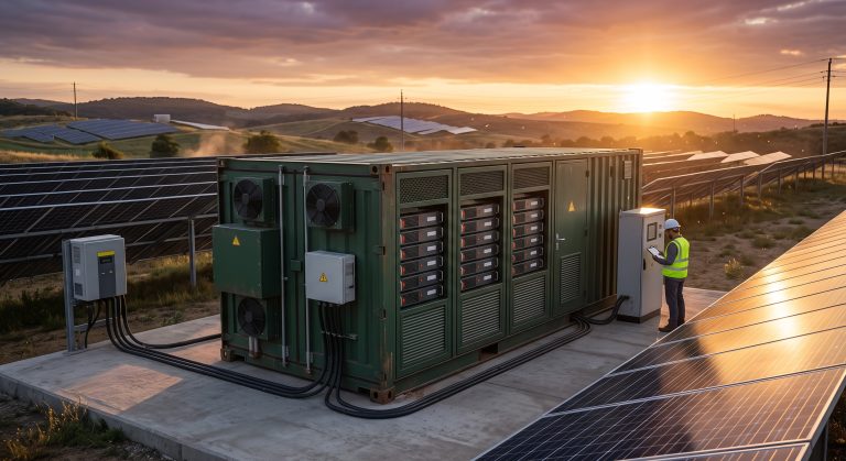
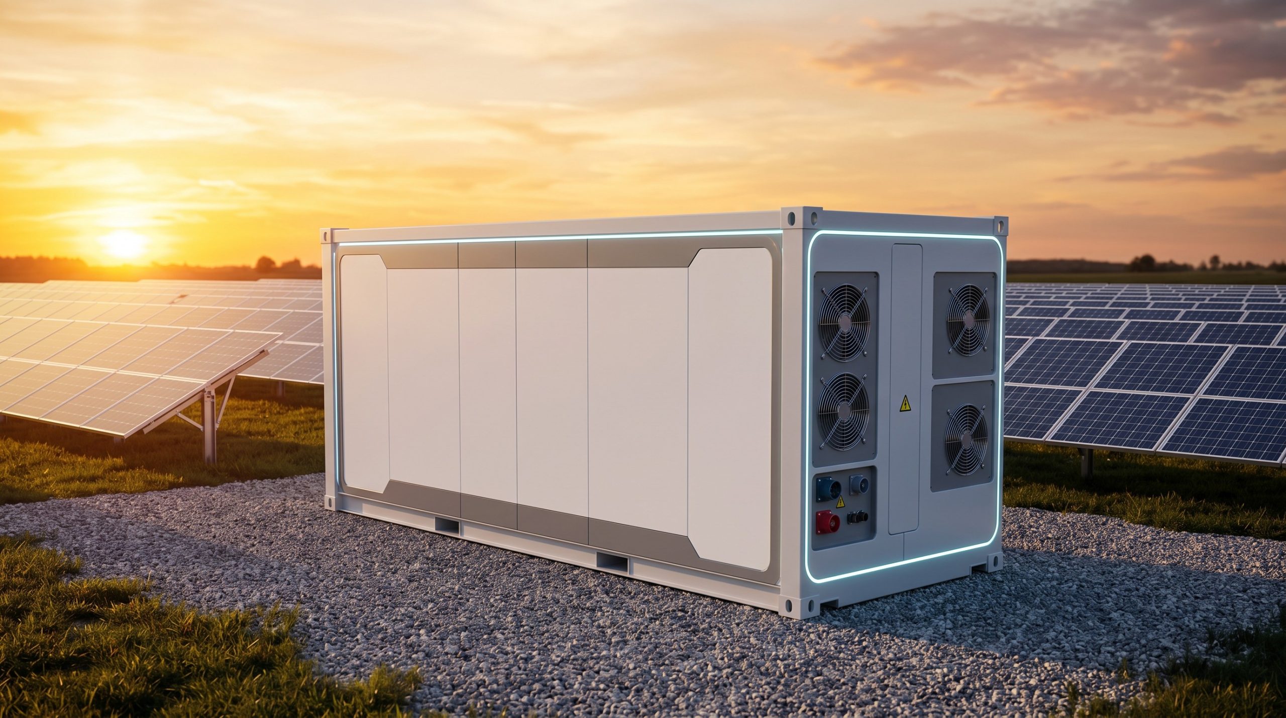
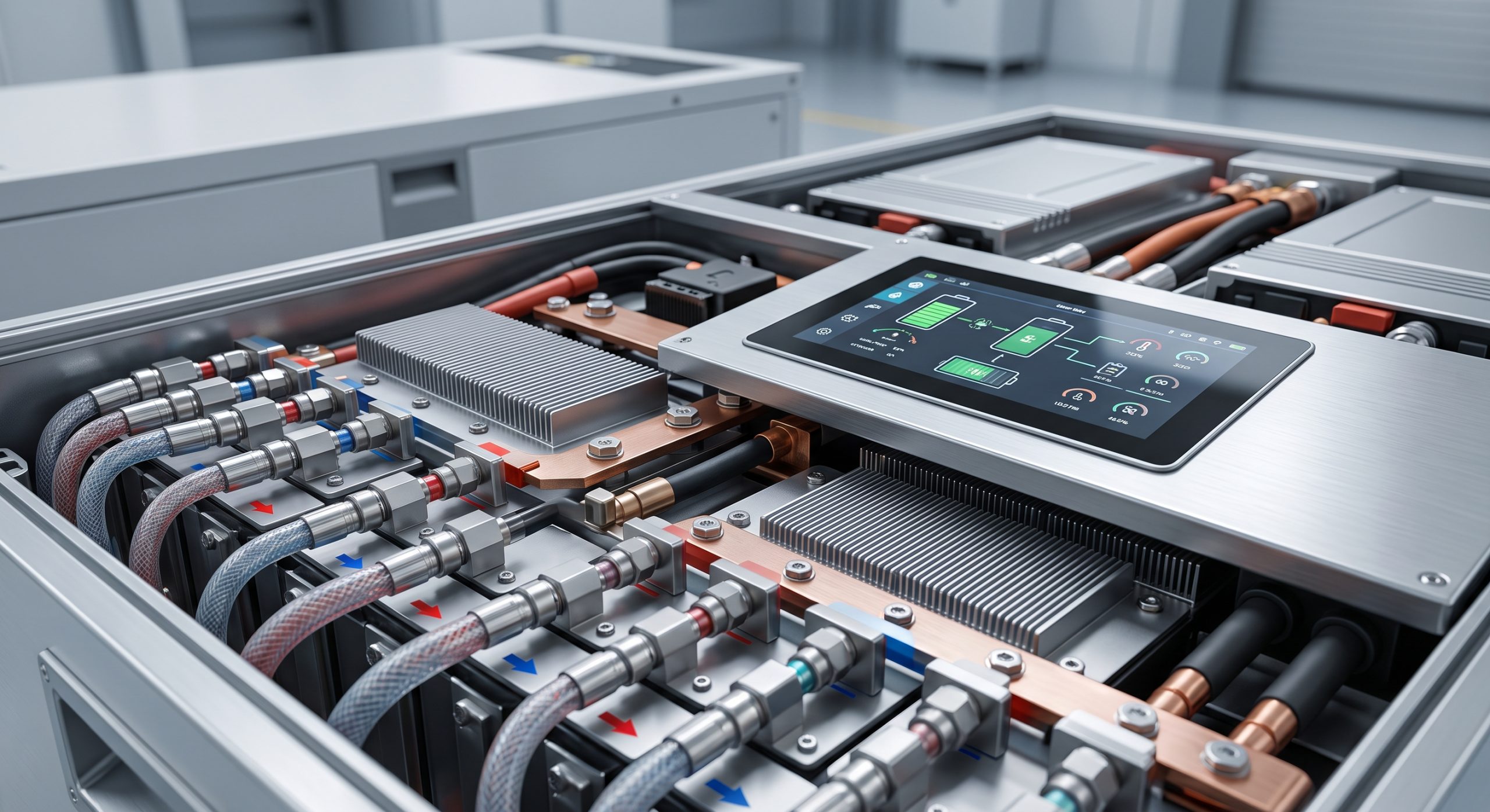
The preventative maintenance schedule assumes a standard C&I BESS architecture comprising: Tier-1 LFP battery modules housed in a liquid-cooled outdoor cabinet or container; a bi-directional PCS; a Battery Management System (BMS) with active cell balancing; a dedicated HVAC or liquid cooling unit; fire detection and suppression systems; and a cloud-connected EMS. Safety is engineered at the cell, module, rack, and system level. The maintenance tasks below are designed to verify that these layers remain functional and that no degradation pathway compromises the system’s safety integrity.
KEY FEATURES
– Tiered Maintenance Intervals: Daily remote monitoring, quarterly on-site inspections, semi-annual functional tests, and annual comprehensive audits.
– BMS-Centric Diagnostics: All maintenance activities are logged and verified through the BMS and EMS, enabling traceable compliance reporting.
– Thermal Management Verification: Liquid cooling loop integrity, coolant quality, and temperature differentials are checked at every scheduled interval.
– Fire Safety Assurance: Detection sensors, suppression agent pressure, and emergency shutdown pathways are tested semi-annually.
– Warranty Preservation: Documented adherence to this schedule is a prerequisite for full warranty coverage on capacity retention and system availability.
COMPLIANCE & STANDARDS
The preventative maintenance schedule is engineered to satisfy the following standards and directives: UL 9540 (Energy Storage Systems and Equipment), UL 9540A (Test Method for Evaluating Thermal Runaway Fire Propagation), IEC 62619 (Secondary Cells and Batteries Containing Alkaline or Other Non-Acid Electrolytes), IEC 62933 (Electrical Energy Storage Systems), NFPA 855 (Standard for the Installation of Stationary Energy Storage Systems), and local grid interconnection requirements. All maintenance records must be retained for the operational life of the asset and made available for inspection by authorities having jurisdiction.
TECHNICAL SPECIFICATIONS
The following table outlines the preventative maintenance schedule, including recommended intervals, responsible parties, and acceptance criteria. Intervals may be adjusted based on site environmental conditions, cycling intensity, and OEM-specific guidance. All activities must be performed by OEM-certified personnel or authorized service partners.
| Maintenance Task | Interval | Responsible Party | Acceptance Criteria |
|---|---|---|---|
| Remote system status review via EMS | Daily | OEM Monitoring Center | No active alarms; SOC and SOH within expected ranges |
| Visual inspection of enclosure, signage, and access | Quarterly | Certified Technician | No corrosion, obstruction, or unauthorized access |
| BMS cell voltage and temperature check | Quarterly | Certified Technician | Cell voltage delta < 50 mV; temperature delta < 5°C |
| Liquid cooling loop pressure and coolant level | Quarterly | Certified Technician | No leaks; pressure within OEM specification |
| HVAC filter cleaning or replacement | Semi-Annual | Certified Technician | Airflow unobstructed; filter condition acceptable |
| Fire detection and suppression system test | Semi-Annual | Certified Technician | Sensors responsive; suppression agent pressure nominal |
| PCS firmware and BMS firmware update check | Semi-Annual | OEM Service Engineer | Firmware current per OEM release schedule |
| Full capacity test and round-trip efficiency audit | Annual | OEM Service Engineer | Capacity retention ≥ warranted curve; RTE ≥ 90% |
| Torque check on DC busbar and power connections | Annual | Certified Technician | All connections within specified torque range |
| Grounding and insulation resistance test | Annual | Certified Technician | Insulation resistance > 1 MΩ; grounding continuity confirmed |
| Emergency shutdown functional test | Annual | Certified Technician | E-stop and remote shutdown operate correctly |
| Thermal imaging of electrical connections | Annual | Certified Technician | No hot spots exceeding 10°C above ambient |
INDUSTRIAL DEPLOYMENT
This schedule is applicable to a wide range of C&I deployments, including peak shaving, demand response, renewable self-consumption, EV charging buffering, and micro-grid support. For sites operating in extreme ambient temperatures, high humidity, or dusty environments, the quarterly inspection frequency should be increased to monthly. For assets participating in frequent deep-cycle arbitrage, additional BMS cell balancing checks are recommended. The OEM reserves the right to update this schedule based on field data and technological improvements; the most current revision is always available through the official service portal.
📥 Download Technical Specification
Click the button below to view or download the full official PDF datasheet.