Introduction: The Hidden Backbone of Commercial Energy Storage
In the rapidly evolving landscape of Commercial & Industrial (C&I) energy storage, system architects and procurement managers often focus on headline metrics: System Capacity (kWh/MWh), Cycle Life, and Round-trip Efficiency. However, the true determinant of a battery energy storage system’s (BESS) safety, longevity, and financial viability often lies in a component that is rarely discussed in boardrooms: the battery module busbar. As a critical current-carrying conductor, the busbar design dictates the internal resistance, thermal profile, and mechanical integrity of the entire battery module. A poorly designed busbar can lead to localized hotspots, increased internal resistance (IR) drops, and premature cell degradation, directly impacting your Levelized Cost of Energy (LCOE) and Return on Investment (ROI).
This comprehensive guide delves into the engineering intricacies of battery module busbar design, exploring how material selection, geometric optimization, and advanced joining techniques contribute to a robust, UL 9540 and IEC 62619-compliant energy storage system. Whether you are deploying a 1 MWh peak-shaving system for a manufacturing plant or integrating a PV-Storage-Charging microgrid, understanding the busbar is essential for minimizing risk and maximizing asset value.
Core Architecture & Battery Management: The Role of the Busbar in Module Integrity
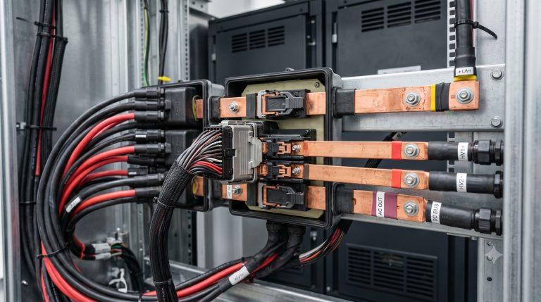
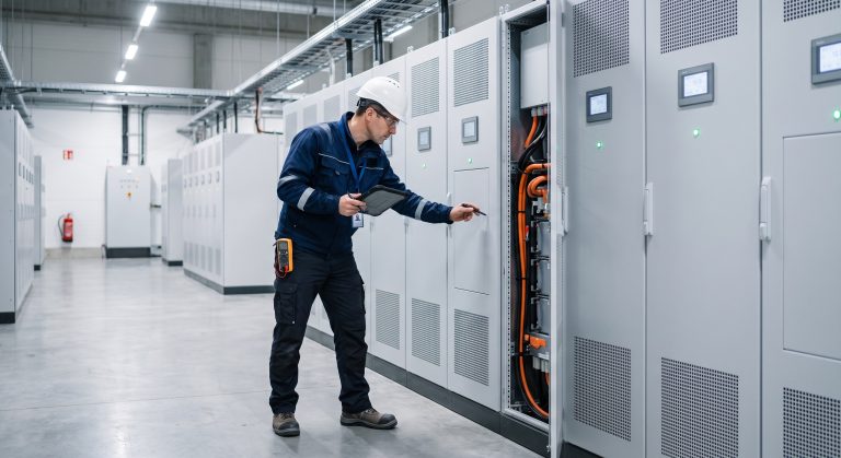
The battery module busbar serves as the electrical spine of a battery module, connecting individual Tier-1 LFP (Lithium Iron Phosphate) cells in a series-parallel configuration to achieve the desired voltage and capacity. Unlike standard cabling, busbars are rigid, low-resistance conductors—typically made of copper or aluminum—designed to handle high currents with minimal voltage drop. In modern C&I BESS, the busbar design must be co-engineered with the Battery Management System (BMS) and Liquid Cooling architecture.
Material Selection: Copper vs. Aluminum
While copper offers superior conductivity (approximately 59.6 million S/m vs. aluminum’s 37.8 million S/m), aluminum busbars are increasingly popular due to their lower density and cost. However, for high-cycle applications requiring >8000 cycles @ 90% DoD, copper is often preferred for its mechanical resilience and resistance to oxidation. The choice directly impacts the Round-trip Efficiency of the system; a 10% reduction in busbar cross-sectional area can increase resistive losses by over 20%, generating excess heat that the Liquid Cooling thermal control system must then dissipate.
Geometric Optimization and Skin Effect
At the high currents typical of MWh-scale deployments, AC ripple and harmonic frequencies can induce the skin effect, pushing current to the outer surface of the conductor. Advanced busbar designs utilize laminated or custom-profiled geometries to maximize surface area and minimize AC impedance. Furthermore, the busbar’s shape must accommodate thermal expansion and vibration. A rigid busbar that does not account for thermal expansion can fatigue solder joints, leading to catastrophic thermal runaway risks. Proper BMS integration requires that the busbar design incorporates voltage and temperature sensing taps at precise locations to ensure cell balancing accuracy.
Technical Specifications: Engineering the Optimal Busbar
When sourcing battery module busbars, procurement teams must evaluate a matrix of technical parameters. The table below outlines the critical specifications that define a high-performance, commercially viable busbar for C&I energy storage. These metrics are essential for ensuring compliance with IEC 62619 and UL 9540 standards.
| Key Parameter | Technical Specification |
|---|---|
| Battery Chemistry | Tier-1 LFP (Lithium Iron Phosphate) |
| Cycle Life | >8000 cycles @ 90% DoD |
| Busbar Material | High-conductivity Copper (C11000) or Aluminum (1060) |
| Busbar Coating | Nickel or Tin plating for oxidation resistance |
| Current Carrying Capacity | Up to 500A continuous per module |
| Contact Resistance | < 0.1 mΩ per joint (laser welded) |
| Insulation Resistance | > 100 MΩ @ 1000V DC |
| Operating Temperature | -20°C to 60°C |
| Thermal Management | Integrated with Liquid Cooling cold plate |
| Compliance | IEC 62619, UL 9540, UN38.3, CE |
| Round-trip Efficiency | > 95% at 0.5C rate |
| System Capacity | 215 kWh to 5 MWh per container |
Beyond the physical specifications, the joining technology is paramount. Laser welding and ultrasonic welding are the industry standards for attaching busbars to cell terminals. Laser welding offers high precision and speed, ideal for automated production lines, while ultrasonic welding provides a solid-state bond with minimal heat-affected zone, preserving the cell’s internal chemistry. For field-serviceable modules, bolted connections with anti-loosening mechanisms and torque monitoring are preferred, though they introduce higher contact resistance if not properly maintained.
Commercial ROI & Grid Support: The Financial Impact of Busbar Efficiency
The financial performance of a C&I energy storage system is inextricably linked to its internal resistance. Every milliohm of resistance in the busbar translates to I²R losses, which manifest as heat and reduced Round-trip Efficiency. For a 1 MW / 2 MWh system performing two cycles per day, a 0.5% improvement in efficiency can yield thousands of dollars in additional revenue annually through peak shaving and demand response programs.
Furthermore, robust busbar design enhances grid support capabilities. During frequency regulation events, the BESS must ramp power output rapidly. A low-impedance busbar ensures that the system can deliver instantaneous power without voltage sag, meeting the stringent requirements of grid operators. This capability is crucial for participating in virtual power plant (VPP) networks, where fast response times are financially rewarded. By minimizing losses, the busbar directly contributes to a lower LCOE, making the business case for battery module busbar design a critical component of the overall project’s financial model.
Deployment Scenarios: From Industrial Parks to EV Supercharging
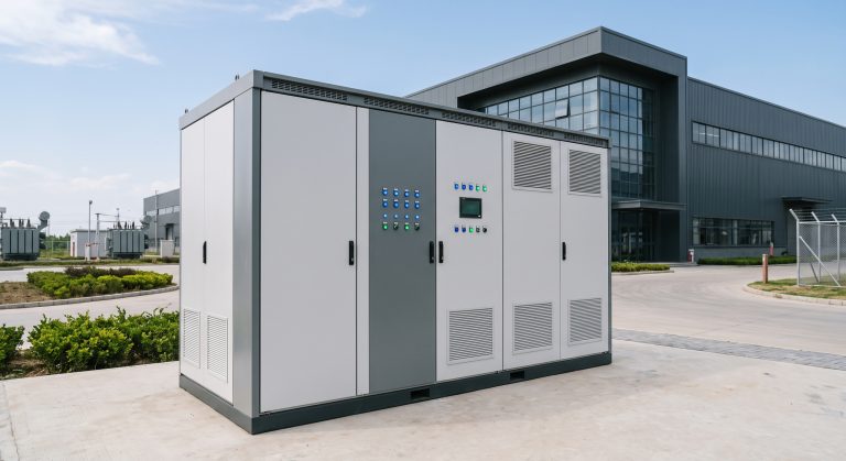
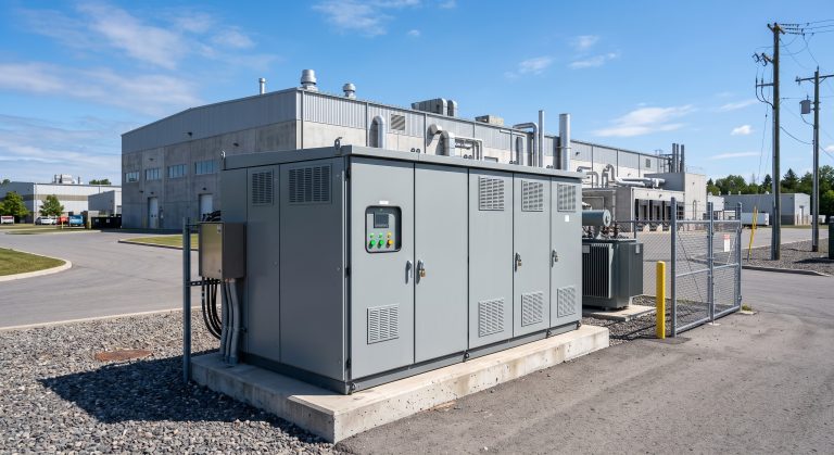
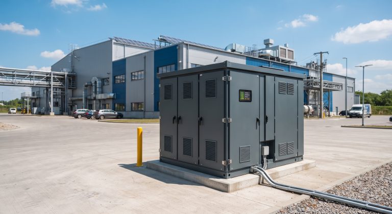
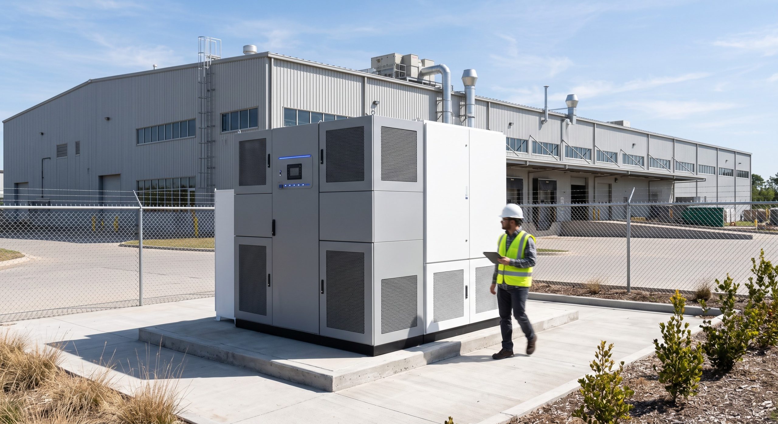
The versatility of advanced busbar designs enables deployment across diverse scenarios. In industrial parks, where space is at a premium, high-density busbar configurations allow for compact containerized outdoor installation, maximizing energy density per square foot. For EV supercharging stations, the busbar must handle high-frequency, high-current pulses. The PV-Storage-Charging synergy requires a busbar that can seamlessly manage bidirectional power flow—from solar canopies to the battery, and from the battery to the EV chargers—without significant thermal buildup.
In zero-carbon migration projects, the busbar’s longevity and maintenance-free design reduce operational expenditures. By eliminating the need for periodic re-torquing of cable lugs and reducing the risk of connection failures, facility managers can achieve higher uptime and energy independence. As the industry moves toward MWh-scale deployment blueprints, the standardization of busbar interfaces will be key to reducing engineering costs and accelerating project timelines.

Conclusion: Strategic Procurement for Long-Term Resilience
The battery module busbar is not merely a passive connector; it is an active enabler of safety, efficiency, and profitability in commercial and industrial energy storage. As you evaluate BESS suppliers, look beyond the cell manufacturer and examine the busbar’s material grade, cross-sectional area, joining method, and thermal management integration. A well-engineered busbar ensures compliance with UN38.3 for transport safety and UL 9540 for stationary installation, while delivering the low internal resistance required for high Round-trip Efficiency and extended Cycle Life.
By prioritizing superior busbar design in your procurement specifications, you safeguard your investment against thermal degradation, maximize your peak-shaving ROI, and ensure your facility is ready for the demands of a decarbonized, grid-interactive future. For B2B buyers, the message is clear: the path to energy independence runs through the busbar.