TURNKEY HARDWARE INTEGRATION & SAFETY SPECIFICATION
This document serves as the authoritative OEM reference for the integration, commissioning, and safety validation of hybrid inverter and battery pairing configurations within commercial and industrial (C&I) energy storage systems. It is intended for system integrators, EPC contractors, and certified installation engineers deploying Tier-1 LFP-based storage assets in grid-tied, off-grid, and micro-grid applications. The manual outlines the electrical, thermal, and communication interfaces required to achieve optimal round-trip efficiency, operational safety, and long-term asset reliability.
PRODUCT IDENTIFICATION
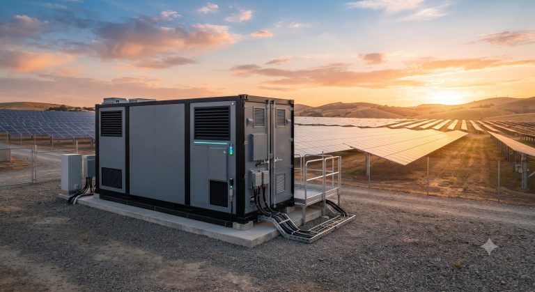
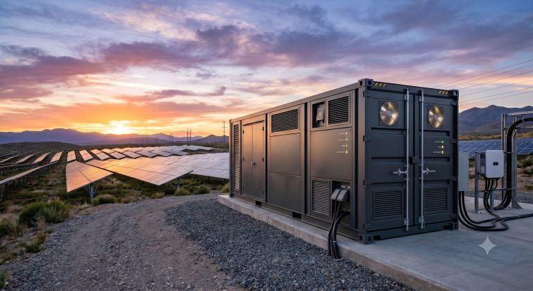
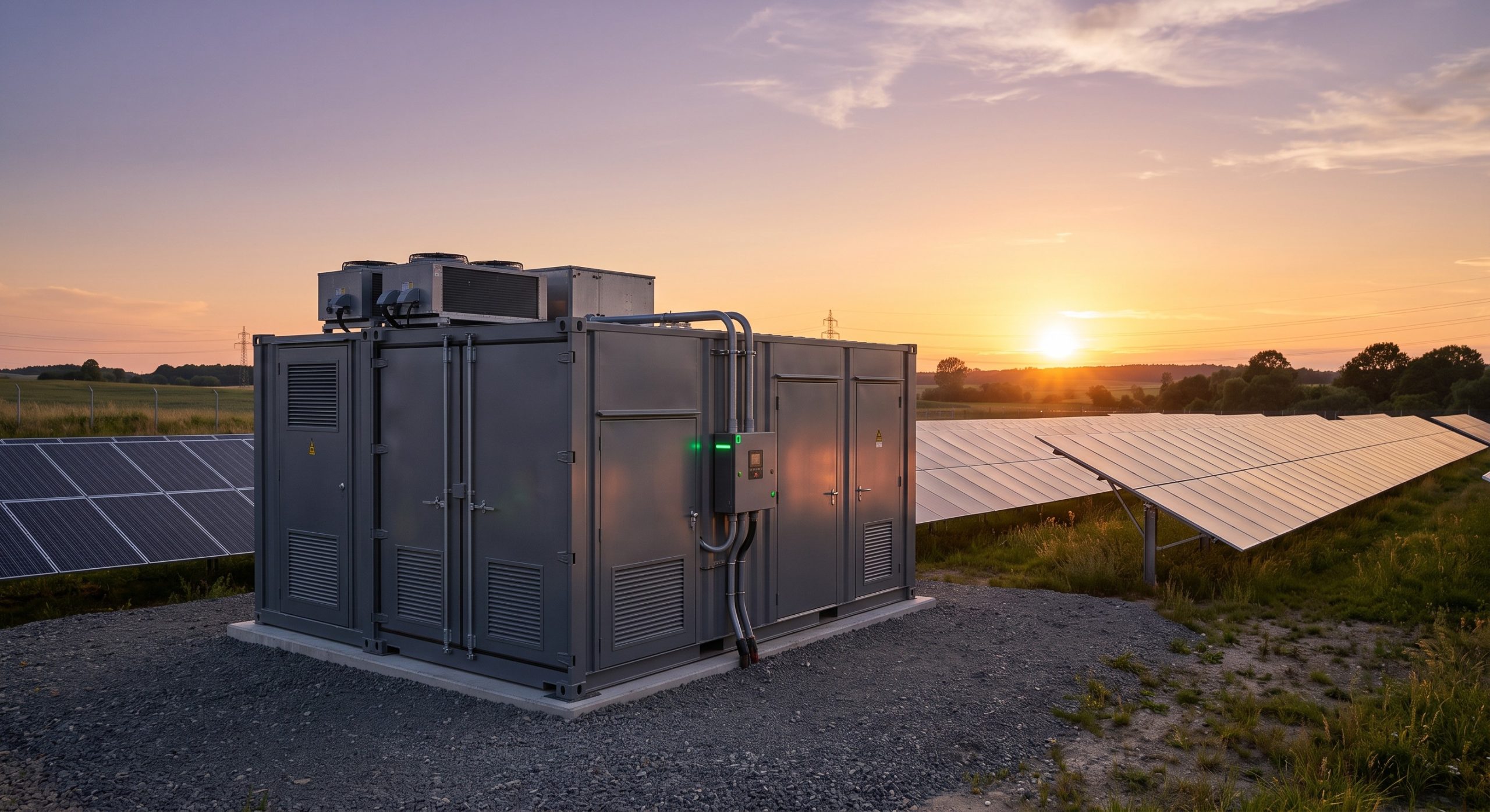
The hybrid inverter platform is a bi-directional power conversion system (PCS) designed for seamless DC coupling with high-voltage battery cabinets. It supports multiple MPPT channels for direct PV integration, an AC-coupled grid interface, and an essential load backup port. The paired battery system utilizes a modular, rack-based architecture with an integrated Battery Management System (BMS) that communicates via CAN 2.0B with the inverter’s Energy Management System (EMS). Each battery cabinet is equipped with an independent fire suppression module, a liquid cooling plate, and a DC disconnect switch to ensure safe isolation during maintenance or fault conditions.
INTERNAL BESS TOPOLOGY
The battery pairing architecture follows a master-slave configuration. The Battery Control Unit (BCU) acts as the master, aggregating cell voltage and temperature data from each Battery Module Unit (BMU). The BMU performs active cell balancing and reports State of Charge (SOC) and State of Health (SOH) to the BCU. The BCU then relays this information to the hybrid inverter via a dedicated RJ45 communication link. The DC busbar is designed for a nominal voltage of 600V to 1000V, with a maximum continuous discharge current of 200A per cabinet. Parallel expansion is supported for up to 8 cabinets, yielding a maximum combined capacity of 1.72 MWh per inverter cluster.
THERMAL PROTECTION MECHANISMS
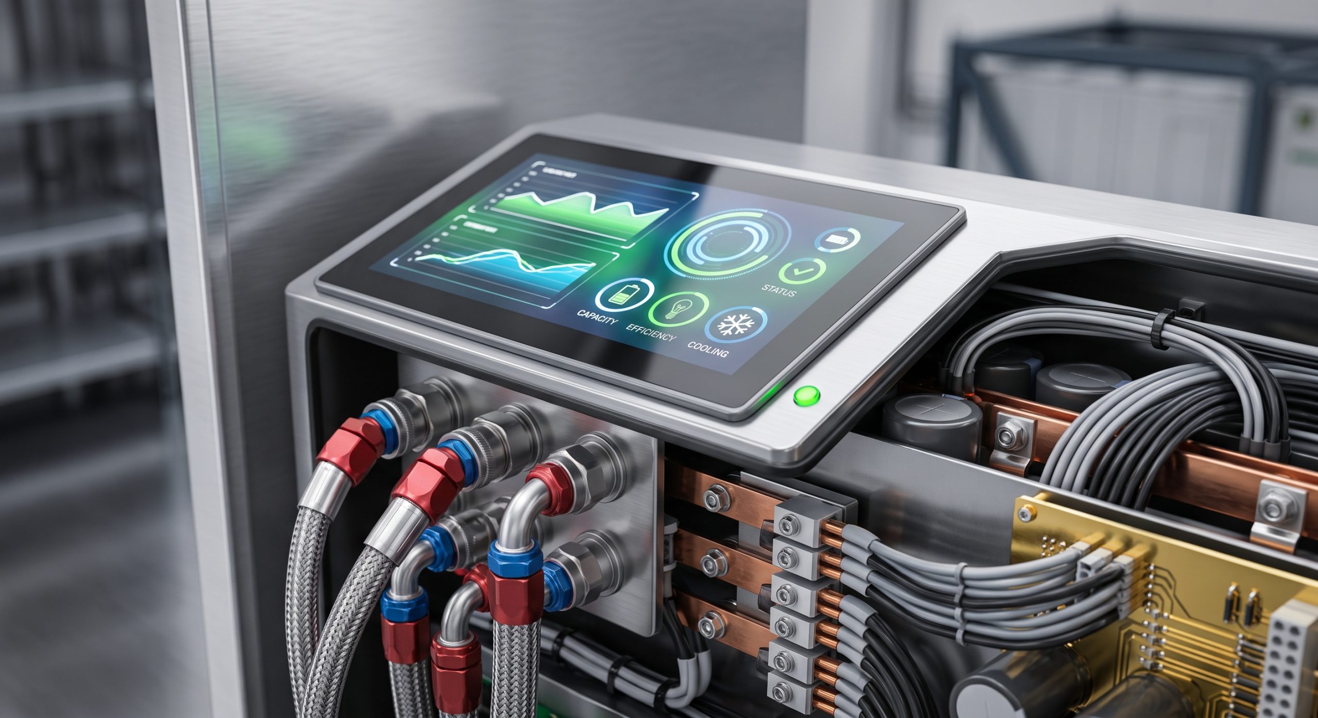
The hybrid inverter employs a forced-air cooling design with variable-speed fans and an IP65-rated heatsink for outdoor deployment. The battery cabinets utilize a smart liquid cooling system with a 50/50 ethylene glycol-water mixture. The cooling loop is managed by an independent Thermal Management Unit (TMU) that maintains cell temperatures within a 3°C delta across all modules. In the event of a thermal runaway detection, the TMU triggers an emergency coolant flush, while the inverter initiates a controlled power derating and eventual shutdown. The battery cabinet’s aerosol-based fire suppression system is designed to suppress propagation in accordance with UL 9540A test criteria.
OPERATIONAL ADVANTAGES
– Seamless Backup Transition: The hybrid inverter achieves a transfer time of less than 20 ms to essential loads during grid failure, ensuring uninterrupted power for critical operations.
– Peak Shaving Optimization: The integrated EMS employs a predictive algorithm that analyzes historical load profiles and time-of-use tariffs to maximize peak shaving revenue.
– PV Self-Consumption Maximization: With dual MPPT trackers and a 150% DC/AC ratio, the system captures excess solar generation for battery charging, reducing grid import during high-tariff periods.
– Remote Firmware Upgrades: Both the inverter and battery BMS support OTA (Over-The-Air) firmware updates via the cloud portal, ensuring the system remains compliant with evolving grid codes.
SPECIFICATION MATRIX
The following table summarizes the key technical parameters for the hybrid inverter and paired battery cabinet. All values are nominal at 25°C ambient temperature unless otherwise specified.
| Parameter | Specification |
|---|---|
| Nominal AC Output Power | 50 kW / 100 kW (configurable) |
| Maximum DC Input Voltage | 1,000 VDC |
| Battery Cabinet Nominal Voltage | 768 VDC |
| Battery Cabinet Capacity | 215 kWh / 372 kWh (optional) |
| Cell Chemistry | Tier-1 LFP (Lithium Iron Phosphate) |
| Cooling Method | Smart Liquid Cooling (Battery) / Forced Air (Inverter) |
| Communication Interface | CAN 2.0B / RS485 / Ethernet |
| Ingress Protection | IP65 (Inverter) / IP55 (Battery Cabinet) |
| Operating Temperature Range | -20°C to +55°C (derating above +45°C) |
| Cycle Life | ≥ 6,000 cycles @ 80% DoD, 25°C |
| Certifications | UL 9540, IEC 62619, IEC 62109, CE |
REGULATORY COMPLIANCE
The hybrid inverter and battery pairing manual complies with the following international standards: IEC 62109-1/-2 (Safety of Power Converters), IEC 62477-1 (Safety of Power Electronic Converter Systems), UL 1741 SA (Inverters, Converters, Controllers), UL 9540 (Energy Storage Systems and Equipment), IEC 62619 (Secondary Cells and Batteries for Industrial Applications), and IEC 63056 (Secondary Cells and Batteries for Use in Electrical Energy Storage Systems). The system also holds CE and RCM marks for European and Australian markets.
📥 Download Technical Specification
Click the button below to view or download the full official PDF datasheet.