Overview
Insulation resistance (IR) testing is a critical safety and predictive-maintenance function integrated into modern Battery Management Systems (BMS) for commercial and industrial BESS. This FAQ addresses the most common technical, procurement, and post-sales questions plant engineers and EPCs ask about IR monitoring, EMS integration, and fault isolation. Whether you are specifying a new system or troubleshooting an existing installation, these expert answers cover the essentials of BMS insulation resistance testing, monitoring platforms, and grid-tie safety compliance.
Frequently Asked Questions
- Q1: What insulation resistance testing is integrated into the BMS?
- The BMS integrates continuous online insulation resistance (IR) monitoring between the DC bus and earth ground, typically using an unbalanced bridge or injection method to detect leakage currents before they become hazardous. This active monitoring measures IR in real time (often 0–1000 kΩ range) and triggers alarms or contactor opening when values fall below configurable thresholds, such as 100 Ω/V or 500 kΩ per IEC 62619 and UL 9540. Unlike periodic manual megohmmeter tests, this integrated approach provides 24/7 protection against ground faults, cable degradation, and moisture ingress.
- Q2: How does the BMS distinguish between normal capacitive leakage and a genuine insulation fault?
- The BMS uses DC injection or low-frequency signal analysis to separate resistive leakage from capacitive coupling, ensuring accurate IR readings even with long DC cables and inverter noise. It applies filtering algorithms and compares positive-to-ground and negative-to-ground resistance values; a genuine fault shows a sustained drop in one or both directions, while capacitive effects appear only during transients. Advanced BMS platforms also trend IR values over time, enabling predictive maintenance alerts when resistance gradually declines due to aging or humidity.
- Q3: Can the BMS insulation resistance test run while the battery is actively charging or discharging?
- Yes, integrated IR monitoring operates continuously during charge, discharge, and idle states without interrupting normal operation. The measurement circuit is isolated and designed to work across the full DC voltage range, so it does not interfere with PCS or EMS dispatch. This is a major advantage over manual testing, which typically requires shutdown and disconnection. For grid-tie and off-grid configurations, continuous IR monitoring helps prevent nuisance tripping and ensures seamless islanding transitions.
- Q4: What IR threshold should trigger a BMS alarm versus a contactor trip?
- A common two-stage approach is used: a warning alarm at 100–500 kΩ and a protective trip at 50–100 kΩ or below 100 Ω/V, depending on system voltage and local codes. The exact thresholds are configurable in the BMS firmware and should be set according to IEC 62619, UL 9540, and site-specific risk assessments. When the trip threshold is reached, the BMS opens the main contactor and sends a fault signal to the EMS, preventing further energy transfer until the fault is cleared.
- Q5: How does the EMS platform display and log insulation resistance data?
- The EMS displays real-time IR values, historical trends, and fault events on its dashboard, with API integration for SCADA and cloud monitoring. Data is typically logged at 1–5 minute intervals or on change-of-state, and can be exported via Modbus TCP, REST API, or MQTT for third-party analytics. Plant engineers can set email or SMS alerts for threshold breaches, and the BMS maintains a non-volatile fault log for post-event diagnostics.
- Q6: Does insulation resistance testing help prevent thermal runaway in LFP BESS?
- Yes, early detection of insulation degradation prevents ground faults and arc faults that can lead to thermal runaway in LFP battery cabinets. By catching moisture ingress, cable chafing, or cell can corrosion before a short circuit occurs, the BMS IR function adds a critical layer of defense alongside gas detection, smoke sensors, and liquid cooling. This is especially important in harsh outdoor IP65+ enclosures and high-humidity industrial environments.
- Q7: How scalable is BMS insulation resistance monitoring across parallel cabinets?
- Each battery cabinet or rack typically has its own IR monitoring circuit, and the master BMS aggregates data across parallel cabinets via DC busbar communication. This allows scalable monitoring from a single 100 kWh unit to multi-MWh installations without losing fault localization. If one cabinet shows low IR, the system can isolate that cabinet while the rest continue operating, maximizing uptime and simplifying maintenance.
- Q8: What maintenance and calibration are required for the BMS insulation resistance function?
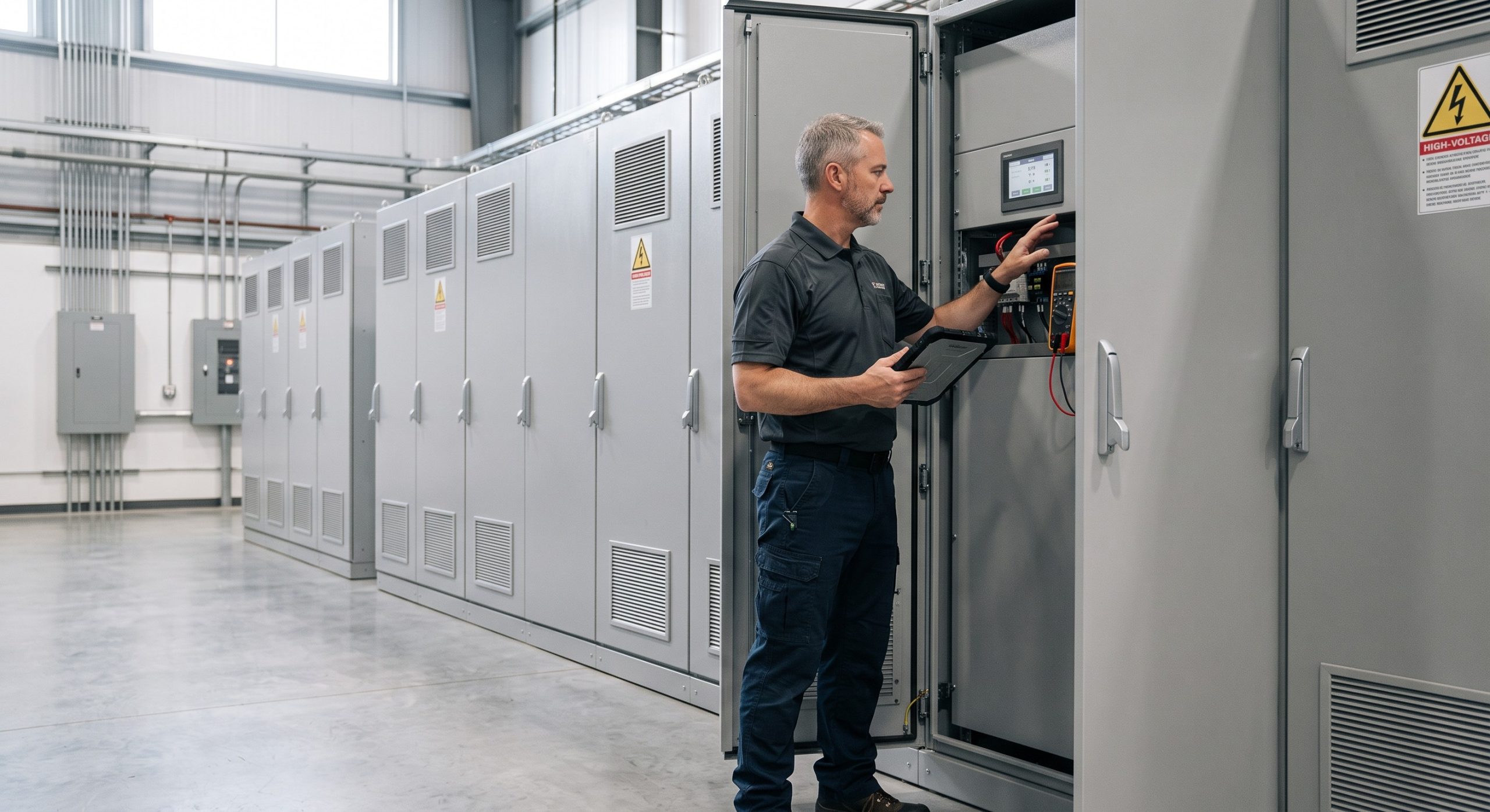
- Integrated IR monitoring requires minimal maintenance, but annual calibration verification with a external megohmmeter is recommended to ensure accuracy. The BMS self-tests its measurement circuit at startup and can flag drift or sensor faults. For post-sales O&M, remote firmware updates and API-based diagnostics reduce the need for site visits, while local lifecycle service teams can replace monitoring modules if needed. Always follow the manufacturer’s calibration schedule and keep logs for warranty compliance.