Overview
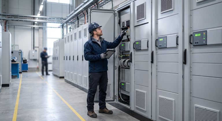
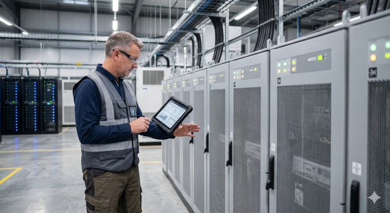
For B2B engineers and procurement specialists, understanding the grounding requirements for a grid-tied containerized Energy Storage System (ESS) is critical for both safety and regulatory compliance. Proper grounding not only protects equipment from fault currents and lightning strikes but also ensures stable BMS communication and grid synchronization. This FAQ addresses the most common technical and commercial questions we receive, from liquid cooling performance to fire safety protocols and ROI calculations.
Frequently Asked Questions
- Q1: What is the standard cycle life and DoD for LFP cells in a grid-tied container ESS?
- The standard cycle life is 6,000 cycles at 80% Depth of Discharge (DoD), extending to 8,000 cycles at 70% DoD. This longevity is achieved through advanced liquid cooling that maintains optimal cell temperatures (23-27°C) and a sophisticated BMS that prevents over-discharge and balances inter-cell voltages, ensuring degradation stays below 20% over 10 years.
- Q2: What are the mandatory grounding requirements for a grid-tied container ESS?
- The system requires a low-impedance earth ground connection (< 1 Ohm) with a dedicated grounding busbar, bonding all metallic enclosures, the PCS chassis, and the transformer neutral point. This must comply with UL 9540 and NEC Article 250 standards, utilizing a solid copper conductor sized per the maximum fault current (typically #2 AWG to 250 kcmil) to ensure safe fault clearing and lightning protection.
- Q3: How does the BMS ensure cell balancing and monitor for thermal runaway risks?
- The BMS provides active, real-time inter-cell balancing with a precision of ±5mV, monitoring voltage, current, and temperature at the cell level every 100ms. For thermal runaway prevention, it uses three-tier protection: early gas detection (CO and H2), rapid temperature rise detection (delta T > 5°C/min), and automatic disconnection of the high-voltage DC circuit within 2ms, isolating the affected module.
- Q4: How do I calculate the ROI and payback period for a containerized BESS with peak shaving?
- ROI is calculated by modeling the daily peak shaving savings (kW saved × demand charge rate) and energy arbitrage (cycling between off-peak and peak energy prices). For example, a 2MWh system shaving 500kW at a $15/kW demand charge generates $7,500/month, yielding a typical payback period of 4-5 years, with system lifespan extending to 15 years.
- Q5: Can the container ESS scale up in capacity, and what is the parallel connectivity limit?
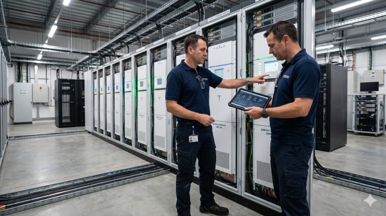
- Yes, the system is modular and scalable. You can connect up to 20 units in parallel via a common DC busbar or AC-coupled architecture. This allows expansion from a 1MWh single unit to a 20MWh site without redesigning the core PCS or EMS, simply by adding cabinets and updating the EMS firmware for synchronized dispatch.
- Q6: What are the fire safety and suppression systems integrated into the container?
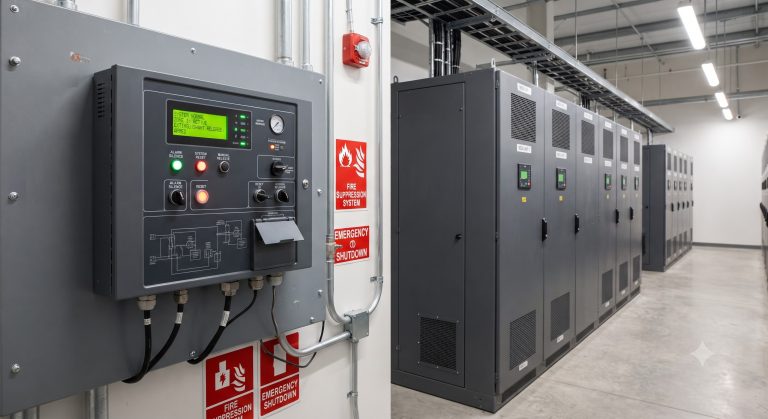
- The container features a multi-tier fire safety system compliant with NFPA 855, including aerosol-based or water-mist active fire suppression, an inert gas (Nitrogen) pre-inerting system, and a 2-hour rated fire-resistant enclosure. The system also includes an early warning gas detection (CO, H2, VOC) that triggers audible/visual alarms and automatically disconnects the grid tie prior to suppression activation.
- Q7: What is the difference in PCS functionality between grid-tied and off-grid configurations?
- In grid-tied mode, the PCS operates in grid-following mode, synchronizing with the utility frequency (50/60Hz) and controlling active/reactive power (PF 0.8 leading/lagging). For off-grid/islanding, the PCS switches to grid-forming mode, acting as a voltage source (V/f control) to establish the local microgrid. The transition between these states is seamless in our hybrid model, switching in less than 20ms.
- Q8: What cooling system does the container use, and how does it maintain optimal battery temperature?
- Our container uses a liquid cooling system with a high-efficiency chiller unit (COP > 3.0) circulating a dielectric coolant through cold plates attached to each battery module. This system maintains the cells within a ±1°C temperature band (22-26°C) across all modules, even at ambient temperatures up to 45°C, ensuring 15% higher cycle life compared to traditional air-cooled systems.