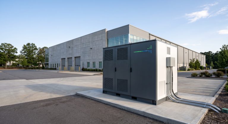
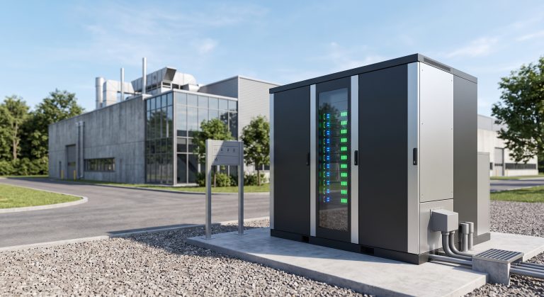
Introduction: The Critical Role of DC Power Connectors in Modern BESS Reliability
In high-voltage commercial energy storage systems (ESS) exceeding 1 MWh, the DC power connector is the single most failure-prone interface. Poor contact resistance leads to thermal runaway, reducing system round-trip efficiency by up to 8% and causing catastrophic arc faults. For system integrators and procurement heads, understanding DC connector architecture—especially under liquid-cooled PCS environments and Tier-1 LFP cell configurations—is mandatory to meet UL 9540 and IEC 62619 compliance.
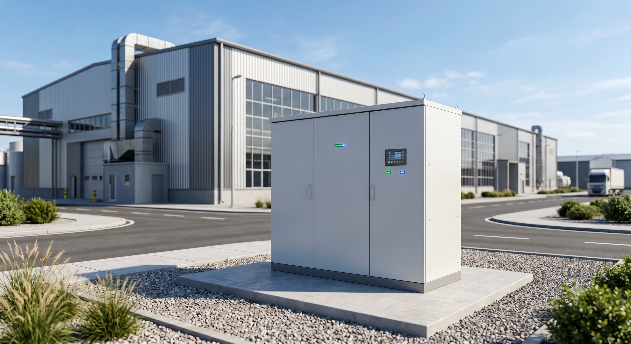
Core Architecture: High-Current DC Connectors in Liquid-Cooled ESS
Voltage & Current Ratings for MWh-Scale Deployments
Modern DC power connectors for C&I storage must support 1500 VDC (IEC 62930 compliant) with continuous current up to 350 A per pole. Liquid cooling integration reduces connector derating: at 45°C ambient, non-cooled connectors lose 20% ampacity, while liquid-cooled PCS busbars maintain >95% rated current. Systems with >8000 cycle life (90% DoD) require connectors rated for >1000 mating cycles with <0.2 mΩ contact resistance drift.
BMS Integration & Cell Balancing
Tier-1 LFP cells demand DC power connectors with integrated NTC thermistor ports for BMS cell voltage monitoring. High-accuracy (≤±1 mV) sensing lines must be isolated from power contacts to prevent EMI corruption. For systems using liquid cooling thermal control, the connector housing must achieve IP67 ingress protection while allowing dielectric coolant circulation around busbars—a design validated by accelerated thermal cycling tests (-40°C to +85°C, 500 cycles).
Technical Specifications: Performance Metrics Under IEC 62619 & UL 9540
The following parameters define bankable DC power connectors for utility-scale ESS. Always request third-party test reports (TÜV, Intertek) verifying these values.
| Parameter | Specification (Compliant to IEC 62619/UL 9540) |
|---|---|
| Rated Voltage | 1500 V DC (max operating 1350 V DC) |
| Rated Current (continuous) | 350 A at 85°C pin temperature |
| Contact Resistance (initial) | <0.15 mΩ (silver-plated copper alloy) |
| Temperature Rise | <50 K at rated current (IEC 60512-5-2) |
| Durability (mating cycles) | >1000 cycles with ΔR <0.05 mΩ |
| IP Protection (mated) | IP67 (with sealing cap), IP2X (unmated) |
| Short-circuit rating | 20 kA for 1 second (UL 4128) |
| Flammability rating | UL94 V-0 (housing) + VW-1 (cables) |
| Certifications | UL 4128, IEC 62852, CE, UN38.3 (transport) |
| Operating temperature | -40°C to +105°C (with liquid cooling: -40°C to +125°C) |
Commercial ROI: Reducing OpEx Through Connector Optimization
High-resistance DC power connectors increase O&M costs by 15-20% annually due to energy loss and premature PCS FET failure. A 500 kWh/1 MWh system with 0.5 mΩ per connector (typical for UL-listed parts) vs 0.2 mΩ (premium tier) saves 3.2 MWh/year in thermal losses—equivalent to $640/year per connector pair at $0.20/kWh. Over 10-year asset life, this improves LCOE by $0.012/kWh, critical for peak shaving ROI breakeven below 4 years.
Deployment Scenarios: Industrial Parks & EV Supercharging Hubs
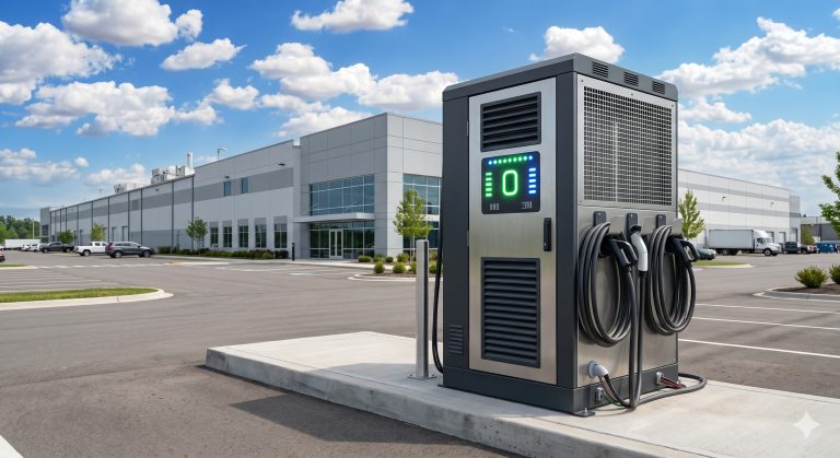
In PV-storage-charging microgrids, DC power connectors link the DC-coupled battery to bidirectional PCS and PV combiner boxes. For EV supercharging stations requiring 350 kW CCS outputs, parallel connector topology reduces voltage drop to <1% at 1200 A peak load. Liquid-cooled DC connectors are now mandatory for >800 V systems, as validated by UL 9540A fire testing.

Conclusion: Procurement Strategy for DC Power Connectors
Specify DC power connectors with published thermal derating curves (IEC 60512-5-2) and witness connector temperature rise testing (<55°C above ambient at rated current). Demand UL 4128 certification and supplier-provided cycle life data. For Tier-1 LFP cells and liquid-cooled PCS, only connectors with silver-plated copper contacts and independent mechanical coding (to prevent HVIL bypass) guarantee 15-year system availability.