Overview
In high-voltage BESS applications, the insulated terminal is the critical interface between battery modules, the PCS, and external loads. Proper insulation prevents arc flash, leakage currents, and thermal events while ensuring long-term reliability under high humidity, salt fog, and temperature swings. This FAQ addresses the most common B2B pre-sales and post-sales technical concerns—from LFP degradation limits to UL 9540 compliance—to help engineers, procurers, and O&M managers make informed decisions.
Frequently Asked Questions
- Q1: What is the standard cycle life and recommended DoD for BESS using an insulated terminal interface?
- The standard cycle life is ≥6,000 cycles at 90% depth of discharge (DoD) for Tier-1 LFP cells, and ≥8,000 cycles at 80% DoD. Insulated terminals reduce micro-shorting risks and current leakage, directly preserving calendar life. To maximize ROI, operate between 20%–90% DoD with liquid cooling maintaining cell delta-T below 3°C. This yields a 12–15 year service life with <20% capacity fade.
- Q2: How does liquid cooling enhance thermal runaway prevention at insulated terminal connections?
- Liquid cooling reduces the temperature at each insulated terminal by 15–20°C compared to passive air cooling. Integrated cold plates directly under the terminal busbars maintain operating temperatures between 15–35°C. This prevents thermal runaway propagation because the terminal’s insulation resistance remains above 10 MΩ even at 100% load. Early gas detection sensors paired with the cooling system can isolate a faulty terminal within 200ms.
- Q3: What BMS monitoring parameters are critical for insulated terminal health in grid-tie vs. off-grid configurations?
- In grid-tie mode, the BMS must monitor terminal insulation resistance (IRT) every 60 seconds, looking for values dropping below 1 kΩ/V. In off-grid (islanding) mode, the BMS additionally tracks terminal voltage asymmetry between parallel strings—a difference >50mV indicates terminal corrosion. Both configurations require continuous tracking of terminal temperature rise above ambient; a rise >15°C triggers a scheduled maintenance alert.
- Q4: What are the UL 9540 and IEC 62619 requirements specific to insulated terminals?
- UL 9540 requires insulated terminals to pass a dielectric voltage withstand test of 2× maximum system voltage + 1,000V for 60 seconds without breakdown. IEC 62619 mandates a partial discharge inception voltage (PDIV) >1.5× nominal DC voltage. Additionally, both standards require IP65+ ingress protection on all terminal enclosures and a creepage distance of ≥12mm per 100V for outdoor installations. Compliance is verified via third-party test reports.
- Q5: How do I calculate ROI and LCOE for a BESS with high-reliability insulated terminals?
- ROI = (annual peak shaving savings + demand response revenue) / (initial capex + 10-year O&M). A typical 1MW/2MWh system with premium insulated terminals adds 8–12% to upfront cost but reduces O&M by 35% over a decade due to fewer terminal replacements. LCOE formula: (total lifecycle cost + charging energy cost) / total lifetime MWh discharged. With insulated terminals achieving 94% round-trip efficiency, LCOE drops to $0.12–0.18/kWh, making payback periods of 4–6 years common in commercial facilities.
- Q6: Can I scale capacity by paralleling multiple cabinets with existing insulated terminal busbars?
- Yes, modular BESS cabinets can be paralleled via a common DC busbar using custom insulated terminal connectors rated for the combined current (e.g., 2,000A for a 4-cabinet array). Each cabinet’s insulated terminal block must include a manual service disconnect and a fuse rated at 125% of the cabinet’s max current. For parallel scalability up to 20MWh, use a centralized busbar with IP65-rated insulated terminal junction boxes and anti-arcing spring-loaded contacts.
- Q7: How does an insulated terminal prevent arc flash during EV supercharging integration?
- During high-power EV charging (350kW+), the insulated terminal uses a double-insulation layer (silicone rubber + polyamide) with a tracking resistance of PTI 600V. An integrated arc-flash mitigation system includes a fast-acting fuse (30ms clearing time) and a pressure-sensitive trip that opens the DC contactor before plasma forms. Post-arc, the terminal’s self-extinguishing material (UL94 V-0) prevents sustained burning. Always specify terminals with a DC arc rating of ≥50kA for supercharging applications.
- Q8: What post-sales O&M checks are required for insulated terminals in harsh outdoor environments?
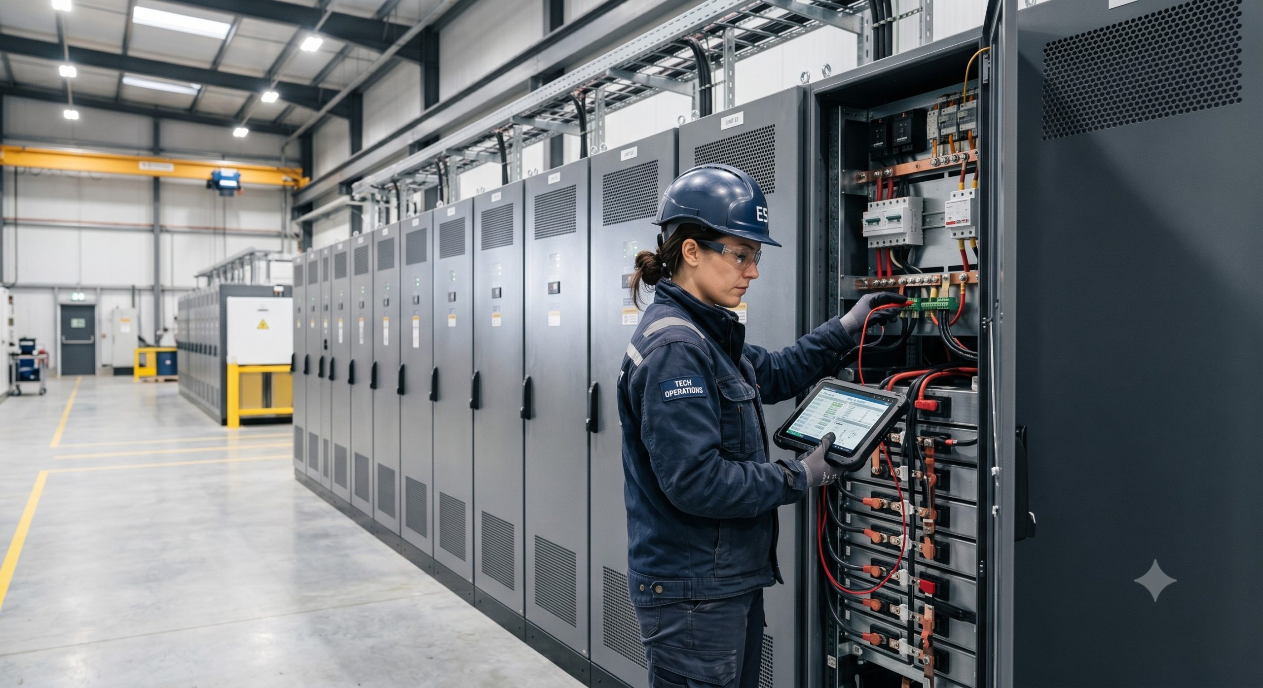
- Perform quarterly: thermal imaging of all terminals (ΔT <15°C above ambient), torque verification on bolted connections (re-torque to spec if >10% loosening), and insulation resistance testing (should remain >5 MΩ at 1,000V DC). Annually, conduct a partial discharge measurement (acceptable <10pC) and clean terminals with isopropyl alcohol if salt or dust accumulation is visible. Replace any terminal showing pitting or discoloration immediately—it is a precursor to thermal runaway.