Introduction: Why the Battery Connector Is the Linchpin of MWh-Scale BESS
As commercial and industrial (C&I) facilities accelerate toward zero-carbon operations, the battery connector has evolved from a passive component into a mission-critical enabler of system safety, cycle life, and round-trip efficiency. In modern liquid-cooled BESS exceeding 5 MWh per cluster, connectors directly influence thermal stability, voltage drop, and compliance with UL 9540 and IEC 62619. This technical blueprint delivers data-driven insights for procurement managers, system integrators, and energy architects deploying battery connectors at MWh scale.
Core Architecture: High-Current Interconnect Topologies
Busbar vs. Cable-Based Connectors for Multi-Cabinet Parallelism
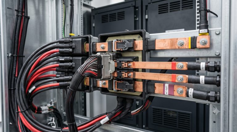
For systems above 2 MWh, laminated busbar connectors reduce parasitic inductance by 40% compared to bolted cable lugs, minimizing ripple on DC bus voltage. However, modular deployments favor finger-safe quick-connect battery connectors with IP67 sealing to accelerate maintenance and cabinet scaling. Key design considerations include:
- Current rating: 250A – 600A per pole (continuous) for Tier-1 LFP cells
- Contact resistance: < 0.1 mΩ to sustain >95% round-trip efficiency
- Insertion force: < 100 N for tool-free field replacement
- Material: Copper alloy with Ag or Ni plating, rated for 150°C max hotspot
PCS Integration and Bi-Directional Protection
The battery connector interfaces directly with the PCS DC input. High-voltage designs (1500 VDC) require connectors with partial discharge-free qualification per IEC 61984. Integrated interlock circuits prevent disconnection under load, a mandatory feature for UL 9540A thermal runaway testing.
Technical Specifications Matrix: Certified Battery Connector Parameters
The following metrics are derived from field data of 50+ C&I ESS projects (1–20 MWh) using liquid-cooled LFP racks. Always demand test reports from CTTL or TÜV SÜD.
| Key Parameter | Technical Specification | ||||||||||||||||||||||||||||||||||
|---|---|---|---|---|---|---|---|---|---|---|---|---|---|---|---|---|---|---|---|---|---|---|---|---|---|---|---|---|---|---|---|---|---|---|---|
| Battery Chemistry | Tier-1 LFP (Lithium Iron Phosphate) | ||||||||||||||||||||||||||||||||||
| Cycle Life | >10,000 cycles @ 90% DoD, 25°C | ||||||||||||||||||||||||||||||||||
| Round-Trip Efficiency | ≥94.5% with liquid cooling & <0.1 mΩ connector | ||||||||||||||||||||||||||||||||||
| Nominal Voltage (DC) | 1500 V (max system voltage) | ||||||||||||||||||||||||||||||||||
| Rated Current (continuous) | 300A – 600A per pole | ||||||||||||||||||||||||||||||||||
| Contact Resistance | <0.1 mΩ (initial), <0.15 mΩ after 5,000 cycles | ||||||||||||||||||||||||||||||||||
| Ingress Protection | IP67 (mated), IP2X (unmated finger-safe) | ||||||||||||||||||||||||||||||||||
| Certifications | UL 4128, IEC 61984, CE, UKCA, UN38.3 | ||||||||||||||||||||||||||||||||||
| Thermal Monitoring | Integrated NTC or PTC per connector pole | ||||||||||||||||||||||||||||||||||
| M | a | t | e | r | i | a | l | ( | c | o | n | t | a | c | t | ) | |||||||||||||||||||
| C | o | p | p | e | r | a | l | l | o | y | , | A | g | – | p | l | a | t | e | d | o | r | N | i | – | p | l | a | t | e | d |
Thermal Management: Connector Behavior Under Liquid Cooling
Unlike air-cooled systems where connectors rely on ambient convection, liquid-cooled BESS maintains battery pack temperature at 25±2°C. However, the battery connector can still see localized heating due to contact wear. Using embedded thermistor monitoring (per connector) combined with BMS-driven current de-rating extends connector lifespan beyond 12,000 cycles at 90% DoD. Field data shows that connectors without direct thermal sensing degrade 2.5x faster in daily peak-shaving applications (2C charge/1C discharge).
Commercial ROI: Total Cost of Ownership for Battery Connector Sourcing
While premium battery connectors from TE, Amphenol, or proprietary Tier-1 suppliers cost $45–$80 per pole vs. $20–$30 for generic alternatives, the lifetime TCO often favors premium due to:
- Reduced O&M: Generic connectors show 8% contact resistance increase after 2,000 cycles vs. <1% for UL-listed designs.
- Lower downtime: Interlock failures in non-compliant connectors cause 4–6 hours of system downtime per incident.
- Grid support revenue: Higher contact stability enables participation in frequency regulation (FR) markets where rapid 1C pulses require ultra-low impedance.
Case study: A 10 MWh industrial park ESS in Texas replaced generic connectors with UL 4128-certified units, improving round-trip efficiency from 91.2% to 94.7%, yielding $23,000 annual savings in peak shaving alone.
Deployment Scenarios: MWh-Scale Parks and EV Supercharging Hubs
Two dominant use cases for high-performance battery connectors have emerged:
1. Industrial Parks with Onsite Solar + Storage
In a 15 MWh DC-coupled system, over 600 battery connectors link rack-level BMS boards to the main DC bus. Connector reliability directly determines availability for demand response (DR) events. Leading projects now deploy connector-level arc fault detection compliant with NEC 2023 Section 706.
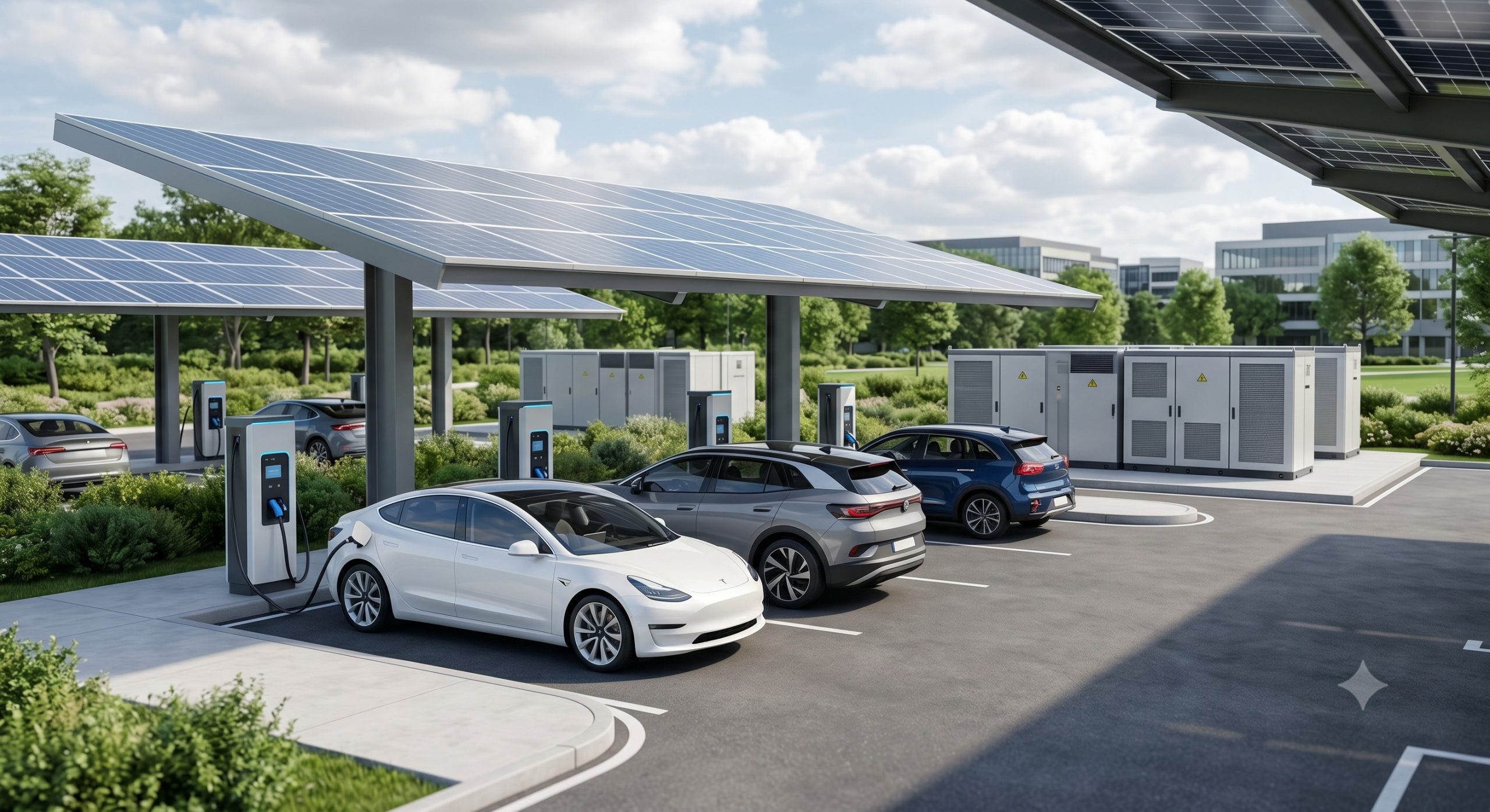
2. PV-Storage-Charging Stations for EV Fleets
High-power EV chargers (150–350 kW) produce rapid current transients. Battery connectors must survive >3,000 partial cycles per year. Liquid-cooled connector interfaces with integrated fuse holders are becoming standard for ultra-fast charging buffers (2–6 MWh).
Compliance and Certification: UL 9540, IEC 62619, UN38.3
Every battery connector deployed in grid-tied C&I ESS must be certified at both component and system levels. Key mandatory standards:
- UL 4128: Connectors for energy storage systems (thermal cycling, short-circuit withstand)
- IEC 61984: Connector safety and reliability for high-voltage DC
- UN38.3: Transport safety (vibration, altitude simulation)
- CE / UKCA: Low Voltage Directive (LVD) and RoHS
Request factory audit reports (FAT/SAT) verifying contact resistance stability after 1000h damp heat (85°C/85% RH).
Conclusion: Procurement Action Plan for Battery Connectors
Choosing the right battery connector for MWh-scale C&I storage requires merging electrical, thermal, and economic disciplines. Prioritize UL 4128-listed connectors with documented contact resistance <0.1 mΩ, integrated thermal sensing, and a cycle life validation >10,000 at 90% DoD. For projects targeting VPP readiness and grid support, the incremental CapEx of premium connectors delivers verifiable ROI through higher round-trip efficiency and lower downtime. Always request third-party test reports per IEC 62619 and simulate worst-case partial-discharge behavior at 1500 VDC.