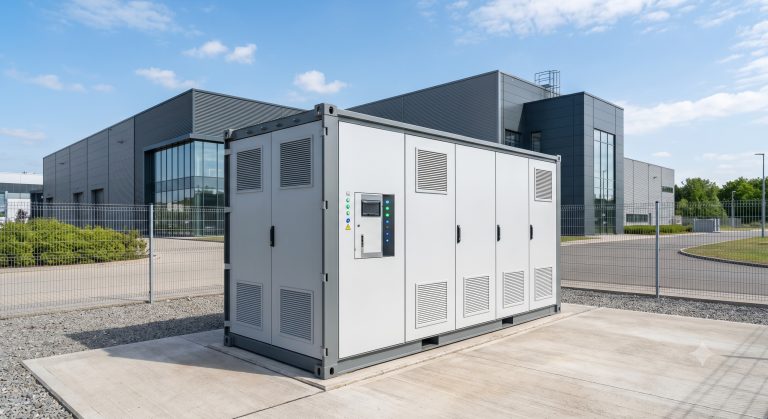
Introduction: The Thermal Management Imperative in Scalable C&I Energy Storage
As commercial and industrial (C&I) facilities accelerate their migration toward scalable C&I energy storage, the engineering spotlight has intensified on a critical determinant of system longevity, safety, and return on investment: thermal management. Unlike residential systems, C&I battery energy storage systems (BESS) routinely operate at MWh-scale capacities, with continuous charge-discharge cycles that generate substantial internal heat. The choice between liquid cooling and air cooling architectures is no longer a peripheral design consideration—it is a foundational decision that impacts round-trip efficiency, cycle life, depth of discharge (DoD) tolerances, and ultimately the levelized cost of storage (LCOS).
This technical deep dive examines the thermodynamic and economic trade-offs between liquid-cooled and air-cooled ESS, with specific reference to Tier-1 LFP (Lithium Iron Phosphate) cell chemistries, IEC 62619 and UL 9540 compliance pathways, and real-world deployment metrics for industrial parks, EV supercharging hubs, and demand-response-enabled microgrids.
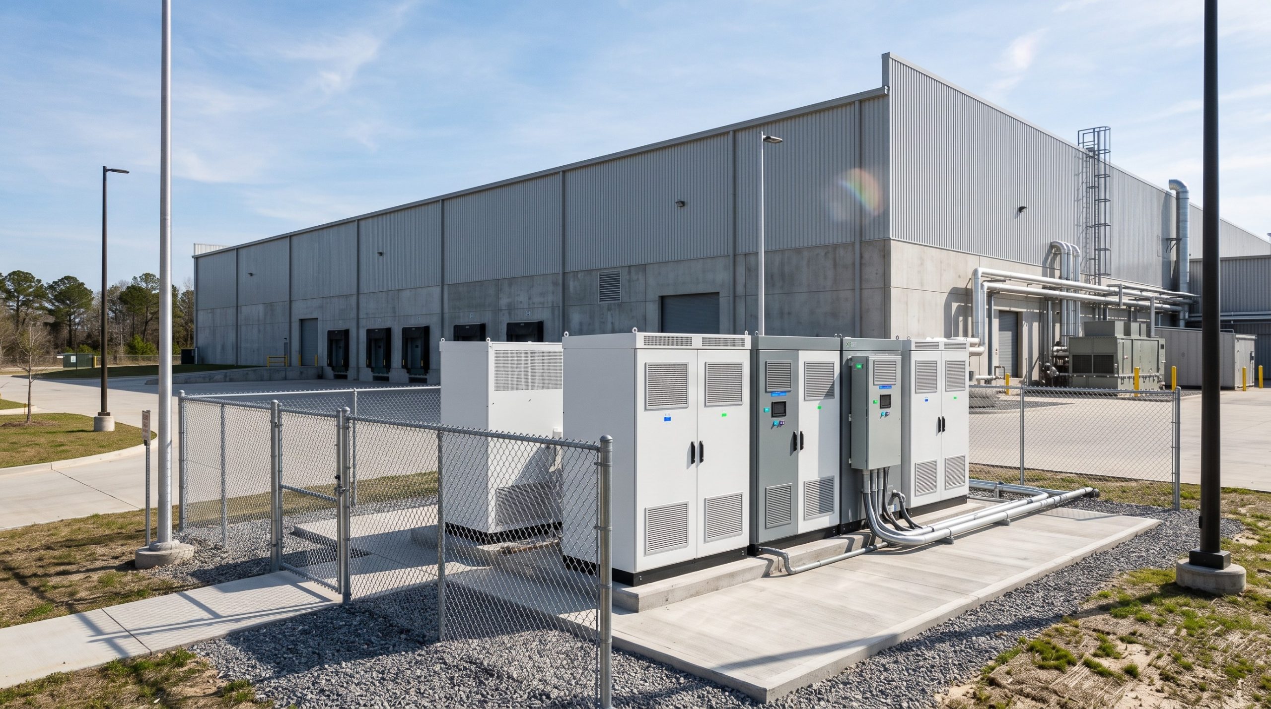
Core Architecture: PCS Integration and Battery Management in High-Density C&I Systems
Bi-Directional PCS and the Thermal Load Challenge
At the heart of any scalable C&I energy storage system lies the power conversion system (PCS), which manages bi-directional energy flow between the battery bank and the grid or local loads. Modern PCS units for C&I applications typically operate at 95-98% efficiency, but the remaining 2-5% of energy is dissipated as heat—a figure that scales linearly with system capacity. For a 1 MW / 2 MWh containerized BESS, this translates to 20-50 kW of continuous thermal load that must be managed to prevent cell degradation and thermal runaway propagation.
BMS Precision and Cell Balancing
The battery management system (BMS) serves as the central nervous system, continuously monitoring cell voltage, temperature, and state of charge (SOC). In liquid-cooled architectures, the BMS integrates with fluid temperature sensors and flow meters to dynamically adjust coolant circulation rates. Advanced BMS algorithms perform active cell balancing, redistributing charge across series-connected cells to mitigate state of charge (SOC) drift—a phenomenon exacerbated by thermal gradients in air-cooled systems. The result is a measurable improvement in usable capacity and a reduction in calendar aging.
Liquid Cooling vs. Air Cooling: Thermodynamic Fundamentals
Air cooling relies on forced convection, typically using fans to circulate ambient or chilled air across battery modules. While simpler and lower in upfront cost, air cooling suffers from low specific heat capacity and uneven temperature distribution, often resulting in cell-to-cell temperature deltas of 5-10°C. Liquid cooling, by contrast, utilizes a dielectric fluid or glycol-water mixture circulated through cold plates or immersion tanks. With a heat transfer coefficient up to 1000 times higher than air, liquid cooling achieves temperature deltas below 3°C, enabling higher continuous C-rates and extending cycle life by 20-40% in high-utilization C&I scenarios.
Technical Specifications: Quantifying Thermal Performance and Safety
The following table summarizes the critical technical parameters that differentiate liquid-cooled and air-cooled scalable C&I energy storage systems. These metrics are derived from Tier-1 LFP cell datasheets and IEC 62619 / UL 9540 test protocols.
| Key Parameter | Technical Specification |
|---|---|
| Battery Chemistry | Tier-1 LFP (Lithium Iron Phosphate) |
| System Capacity | 215 kWh to 5 MWh (modular scalable) |
| Cycle Life | >8000 cycles @ 90% DoD, 25°C |
| Round-Trip Efficiency | ≥92% (liquid-cooled, system-level) |
| Depth of Discharge (DoD) | 90% usable |
| Thermal Management | Liquid cooling (glycol-water, cold plate) |
| Temperature Delta | <3°C cell-to-cell |
| Operating Temperature | -20°C to +55°C (derated above 45°C) |
| Cooling Auxiliary Consumption | 1.5-2.5% of throughput |
| Communication | CAN, RS485, Ethernet (Modbus TCP) |
| Safety Standards | IEC 62619, UL 9540, UN38.3, CE |
| Fire Suppression | Aerosol + perfluorohexanone (Novec 1230) |
| Ingress Protection | IP54 (containerized), IP67 (modules) |
| Certification | UL 9540A (cell, module, unit level) |
Round-Trip Efficiency and Auxiliary Consumption
While round-trip efficiency (RTE) is often quoted at the cell level (typically 95-98% for LFP), system-level RTE is significantly influenced by thermal management parasitic loads. Air-cooled systems in high-ambient-temperature environments (e.g., >35°C) may consume 3-5% of total energy throughput for cooling, reducing net RTE to 88-91%. Liquid-cooled systems, with their superior heat rejection, typically limit auxiliary consumption to 1.5-2.5%, preserving net RTE at 92-94%. Over a 10-year operational horizon, this 2-3% differential can translate to hundreds of MWh of recovered energy for a 2 MWh system—a direct boost to project IRR.
Cycle Life, DoD, and Thermal Derating
Depth of Discharge (DoD) is a critical lever for maximizing asset utilization. Tier-1 LFP cells rated for >8000 cycles at 90% DoD under ideal thermal conditions (25°C) may see cycle life degrade to 5000-6000 cycles if cell temperatures consistently exceed 35°C. Liquid cooling maintains cells within the optimal 20-30°C window, even under 1C continuous discharge, thereby preserving warranted cycle life and minimizing capacity fade. This thermal stability is particularly vital for demand response applications, where rapid, deep discharges are frequent.
Commercial ROI and Grid Support: The Economic Case for Thermal Optimization
Peak Shaving and Demand Charge Reduction
For C&I facilities facing demand charges of $15-30 per kW, scalable energy storage enables peak shaving by discharging during high-load intervals. A thermally optimized system ensures full power availability during these critical windows, without derating. Liquid-cooled systems also support higher continuous power output (e.g., 0.5C to 1C) without thermal throttling, allowing deeper demand charge mitigation.
Frequency Regulation and VPP Readiness
With grid-forming inverters and fast frequency response (FFR) capabilities, scalable C&I ESS can participate in frequency regulation markets, generating ancillary revenue. Thermal management directly impacts response time and sustained power delivery—liquid-cooled systems can maintain 100% power output for 30+ minutes without temperature-induced curtailment, whereas air-cooled systems may derate after 10-15 minutes of high-power operation.
Deployment Scenarios: Industrial Parks, EV Supercharging, and Microgrids
Industrial Park Energy Independence
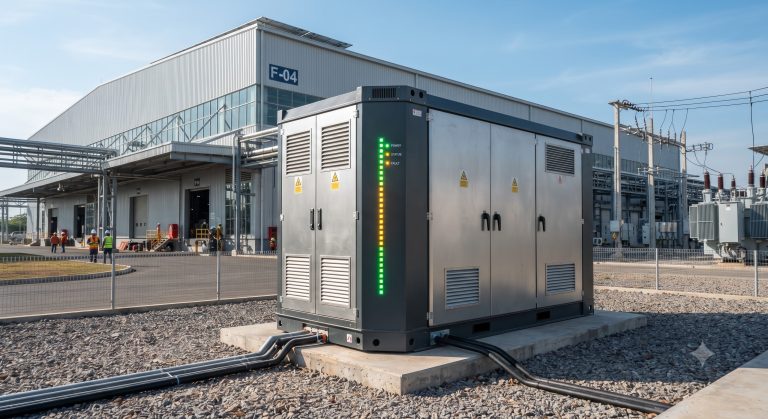
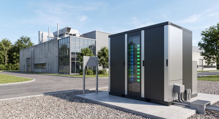
In industrial parks with high simultaneous load factors, modular liquid-cooled BESS cabinets can be paralleled to achieve MWh-scale capacity. The compact footprint of liquid-cooled systems (up to 30% smaller than equivalent air-cooled units) is a decisive advantage where land is constrained. Integration with on-site PV and smart EMS dispatch enables peak shaving, TOU arbitrage, and backup power—all while maintaining UL 9540 and IEC 62619 compliance.
EV Supercharging Stations: PV-Storage-Charging Synergy
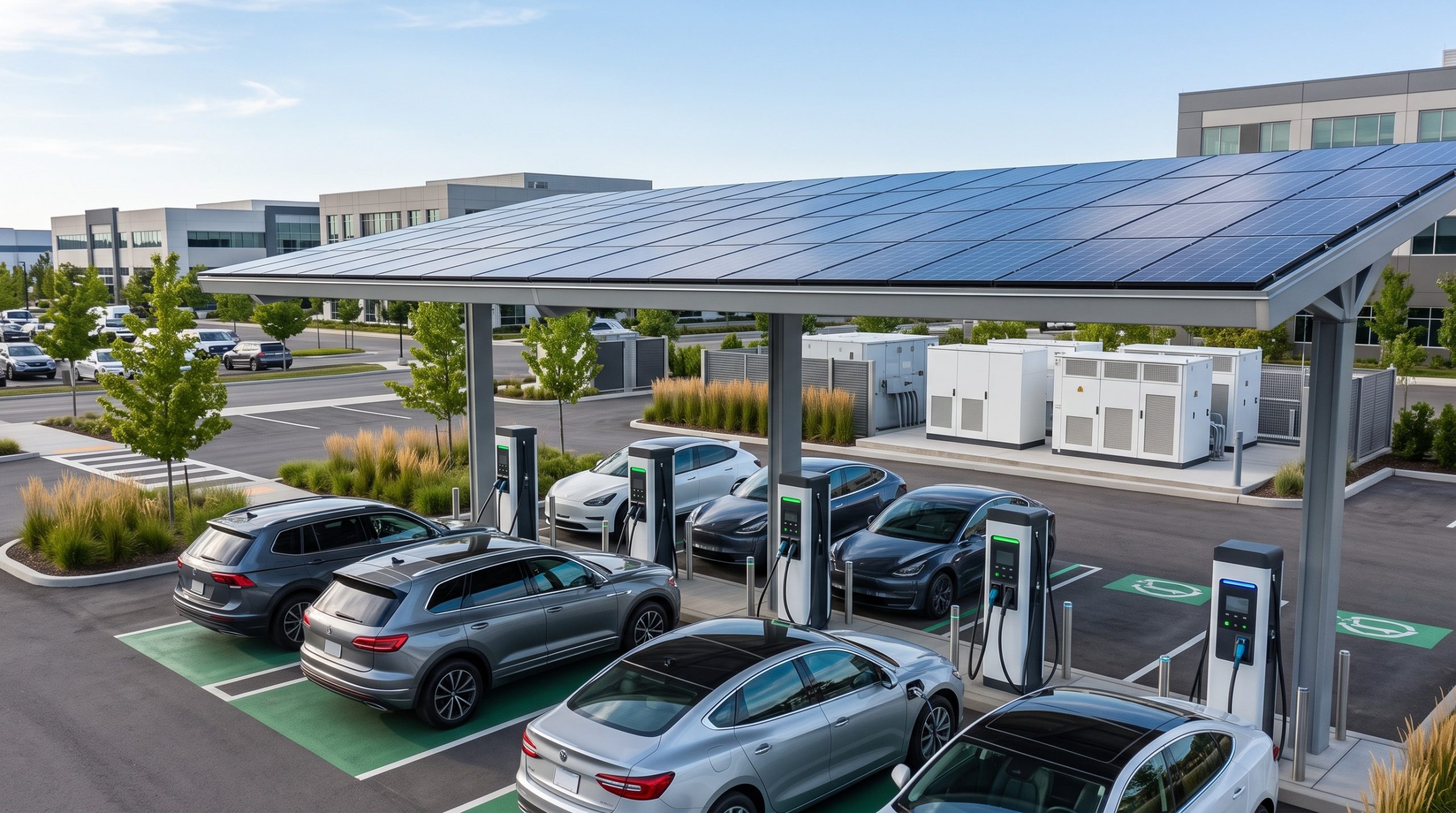
The rollout of 350 kW+ EV superchargers imposes immense pulsed loads on local grids. A PV-storage-charging (光储充) architecture buffers these loads with a liquid-cooled BESS, preventing transformer upgrades and demand charge spikes. The thermal system must handle rapid charge-discharge cycling—often 2-3 full cycles per day—which air cooling struggles to sustain without significant derating. Liquid cooling ensures consistent 1C performance, enabling reliable EV charging during peak hours.
Conclusion: Engineering the Thermal Edge in Scalable C&I Energy Storage
The transition from air cooling to liquid cooling in scalable C&I energy storage is not merely a technological upgrade—it is a strategic imperative for asset owners seeking to maximize cycle life, round-trip efficiency, and commercial returns. By maintaining cell temperatures within ±3°C, liquid-cooled systems unlock higher DoD, faster C-rates, and superior grid support capabilities, all while complying with the most stringent UL 9540 and IEC 62619 safety standards. As demand response markets mature and EV supercharging proliferates, the thermal architecture of your BESS will be a defining factor in its operational and financial performance. For EPCs, asset managers, and facility owners, the data is unequivocal: liquid cooling is the new baseline for high-utilization C&I energy storage.