Introduction: The Strategic Imperative of Lithium Battery Pack Configuration in C&I Energy Storage
As commercial and industrial (C&I) facilities face escalating demand charges, volatile time-of-use (TOU) rates, and aggressive decarbonization mandates, the lithium battery pack configuration has emerged as the single most consequential engineering decision in modern energy storage system (ESS) design. Unlike residential-scale solutions, C&I deployments demand a holistic architecture that balances system capacity (kWh to MWh), cycle life (>8,000 cycles), round-trip efficiency (RTE >92%), and rigorous safety compliance under UL 9540, IEC 62619, and UN38.3. A misconfigured pack topology can erode project LCOE by 15–25%, accelerate capacity fade, and jeopardize grid interconnection approvals. This guide delivers a data-driven framework for CTOs, EPCs, and asset owners evaluating Tier-1 lithium battery pack configuration for peak shaving, demand response, and micro-grid resilience.
Core Architecture: PCS, BMS, and the Science of Cell Balancing
Bi-Directional PCS Integration and DC Bus Topology
The lithium battery pack configuration cannot be evaluated in isolation. It must interface seamlessly with a bi-directional Power Conversion System (PCS) rated for 100–500 kW per cabinet, supporting DC bus voltages of 600–1,500V. String-level Maximum Power Point Tracking (MPPT) is now standard in hybrid PV-storage inverters, enabling DC-coupled architecture that reduces conversion losses by 2–3% versus AC-coupled alternatives. For C&I peak shaving, a 1C to 0.5C discharge rate is typical, dictating cell selection and thermal management strategy.
Battery Management System (BMS): Active vs. Passive Balancing
An advanced BMS governs cell-level voltage (<±10mV tolerance), temperature (<±2°C variance), and State of Charge (SoC) estimation accuracy (<3% error). Active balancing transfers energy between high and low cells, recovering 5–10% of usable capacity over the asset lifetime compared to passive resistive bleeding. For lithium battery pack configuration in high-cycle C&I applications, active balancing is non-negotiable for maximizing Depth of Discharge (DoD) up to 90% without accelerating degradation.
Liquid Cooling vs. Air Cooling: Thermal Control Economics
Thermal runaway prevention and cycle life preservation hinge on thermal control. Liquid cooling maintains cell delta-T within 2–3°C, enabling 0.5C continuous charge/discharge and extending cycle life by 20–30% versus air-cooled systems. Air cooling, while lower CapEx, struggles above 0.3C and in ambient temperatures >35°C. For MWh-scale lithium battery pack configuration, liquid cooling is the default specification for Tier-1 suppliers.
Technical Specifications: A Tier-1 LFP Reference Architecture
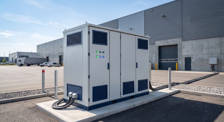
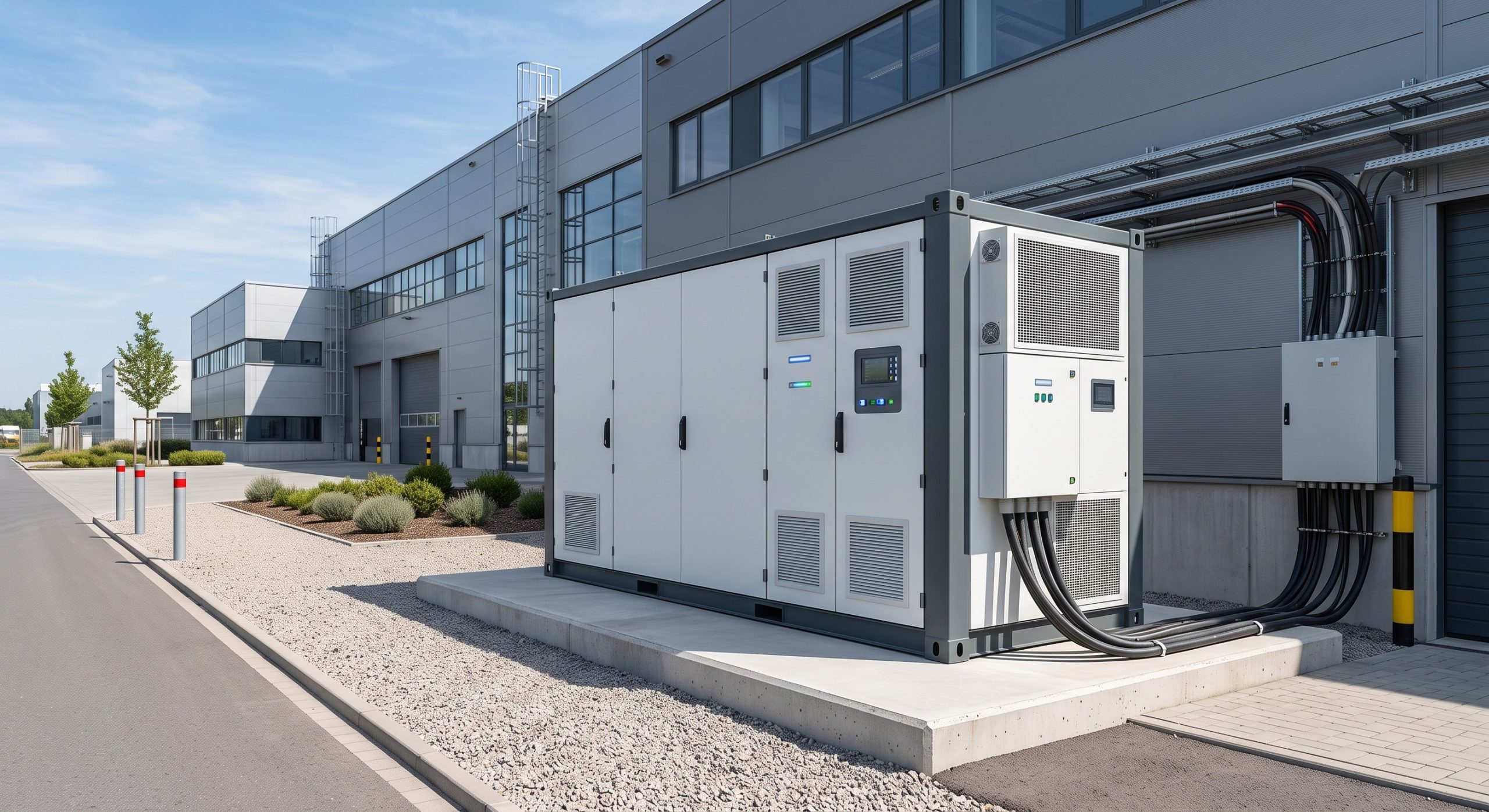
The following specification ledger represents a benchmark lithium battery pack configuration for a 500 kWh / 250 kW C&I cabinet using Tier-1 LFP cells. All parameters are verified against IEC 62619 and UL 9540 test protocols.
| Key Parameter | Technical Specification |
|---|---|
| Battery Chemistry | Tier-1 LFP (Lithium Iron Phosphate) |
| Nominal System Capacity | 500 kWh (expandable to MWh-scale) |
| Cycle Life | >8,000 cycles @ 90% DoD, 25°C |
| Round-Trip Efficiency (RTE) | >92% (DC-DC), >90% (AC-AC) |
| Depth of Discharge (DoD) | 90% maximum recommended |
| Thermal Management | Liquid Cooling, delta-T <2°C |
| BMS Balancing | Active balancing, SoC accuracy <3% |
| PCS Rating | 250 kW bi-directional, 1,500V DC |
| Communication | Modbus TCP/IP, CAN 2.0B, IEC 61850 |
| Safety Standards | UL 9540, IEC 62619, UN38.3, CE |
| Ingress Protection | IP54 (cabinet), IP67 (modules) |
| Operating Temperature | -20°C to +55°C (derated >45°C) |
| Warranty | 10 years / 8,000 cycles (whichever first) |
Commercial ROI & Grid Support: LCOE, Peak Shaving, and Demand Response
LCOE Modeling for C&I Lithium Battery Pack Configuration
Levelized Cost of Storage (LCOS) for a 500 kWh / 250 kW system with >8,000 cycles at 90% DoD and 92% RTE typically ranges from $0.08–$0.12/kWh over a 10-year horizon, assuming $250–$350/kWh CapEx. When stacked with demand response revenues ($50–$150/kW-year) and TOU arbitrage ($0.15–$0.30/kWh spread), payback periods compress to 4–6 years in high-cost markets like California, Germany, and Australia.
Grid Support: Frequency Regulation and VPP Readiness
Modern lithium battery pack configuration must support fast grid synchronization (<100ms response) for frequency regulation (FFR) and Virtual Power Plant (VPP) aggregation. This requires PCS with grid-forming capability and BMS with IEEE 1547 compliant ride-through. For C&I facilities, the ESS can provide peak shaving (reducing demand charges by 30–50%), power factor correction, and backup power during grid outages.
Deployment Scenarios: From Industrial Parks to EV Supercharging
Industrial Park Micro-Grids
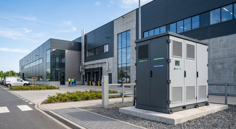
Modular lithium battery pack configuration enables parallel cabinet expansion from 500 kWh to 10 MWh, supporting industrial park energy independence. Inter-cabinet busbar linkage with 1,500V DC architecture minimizes wiring losses and simplifies commissioning.
PV-Storage-Charging (光储充) EV Supercharging Stations
Integrating lithium battery pack configuration with solar canopies and 350 kW DC fast chargers creates a PV-Storage-Charging micro-grid that buffers grid demand, reduces demand charges, and enables off-grid EV charging during peak periods. A 1 MWh ESS paired with 500 kW PV can support 4–6 simultaneous 150 kW charging sessions without grid upgrade.

Conclusion: Sourcing Checklist for Tier-1 Lithium Battery Pack Configuration
Procurement teams should mandate UL 9540, IEC 62619, CE, and UN38.3 certifications, verify cycle life >8,000 @ 90% DoD, demand liquid cooling with <2°C delta-T, and require active BMS balancing with SoC accuracy <3%. A well-engineered lithium battery pack configuration is not a commodity—it is the cornerstone of C&I energy resilience, decarbonization, and long-term ROI. Engage Tier-1 suppliers with proven MWh-scale deployment track records and bankable warranties (10+ years).