EQUIPMENT INTRODUCTION
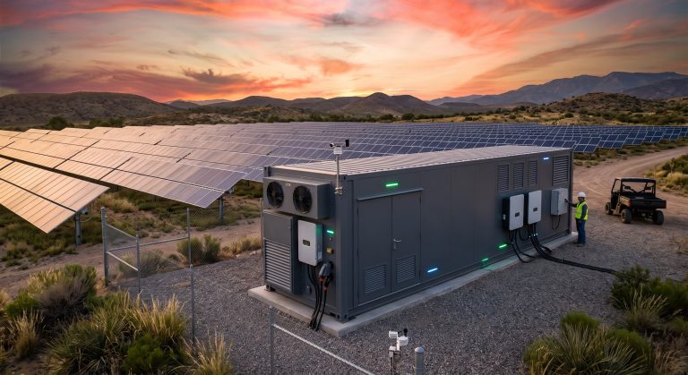
The Containerized Battery Lifting and Handling Guide establishes the mandatory engineering protocols, structural prerequisites, and operational safety directives for the safe movement, staging, and final positioning of MWh-scale commercial Battery Energy Storage System (BESS) containers. As the deployment footprint of Tier-1 liquid-cooled LFP platforms expands into diverse industrial environments, the risk profile associated with heavy-load logistics escalates proportionally. This reference manual serves as the authoritative OEM directive for EPC contractors, logistics partners, and site O&M teams. It delineates the load-bearing capacities, center-of-gravity constraints, and specialized rigging interfaces required to maintain the structural integrity, IP66 sealing, and thermal management pipeline alignment of the containerized asset throughout its entire installation lifecycle. Adherence to these guidelines is non-negotiable to preserve warranty coverage and ensure personnel safety.
OUTDOOR PAD PREREQUISITES
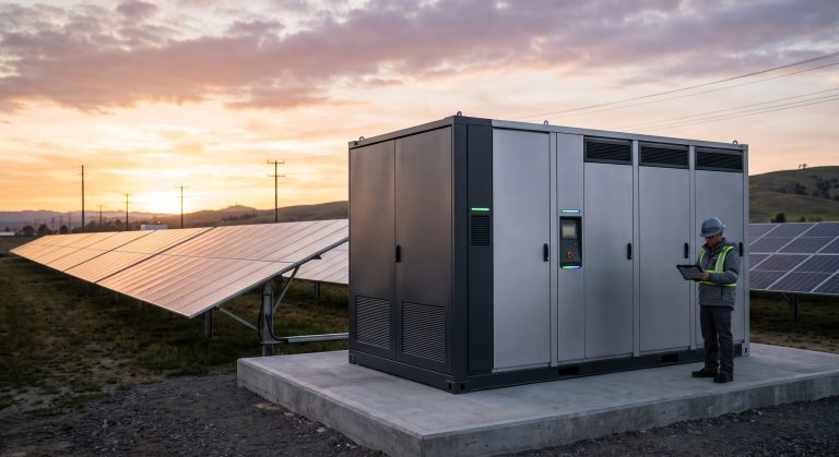
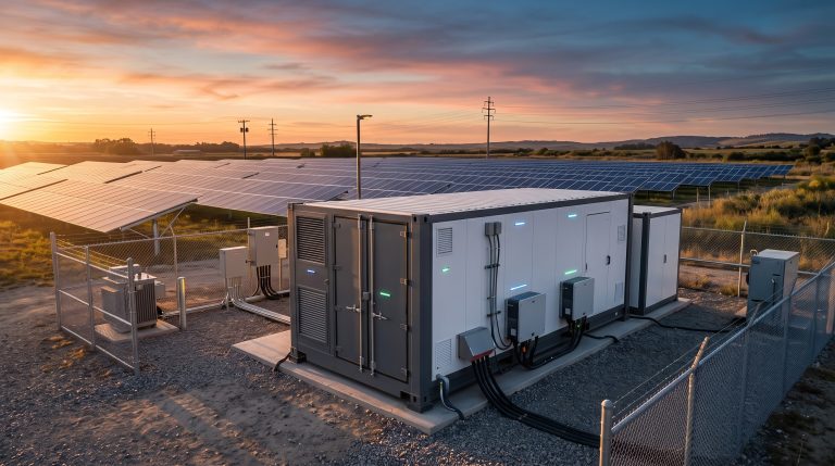
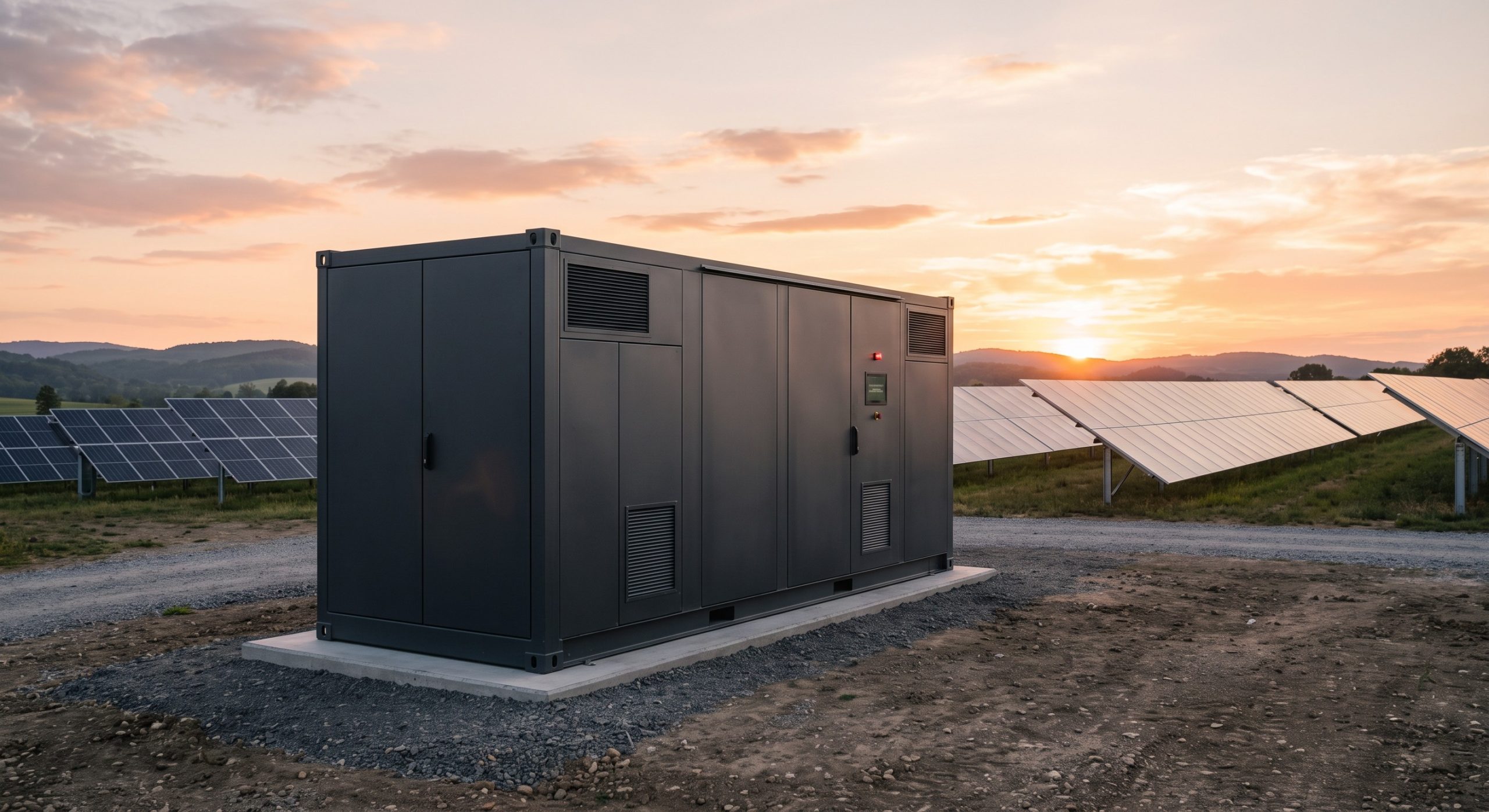
Prior to any lifting evolution, the receiving site must undergo a rigorous geotechnical and topographical validation. The concrete pad or reinforced hardstand must exhibit a uniform load-bearing capacity of no less than 15,000 kg/m² to accommodate the concentrated point loads transmitted through the container’s ISO 1496-1 corner castings and the supplementary mid-span jacking pads. The surface flatness tolerance across the entire footprint must not exceed ±5 mm per 3-meter span to prevent torsional stress on the container chassis and potential misalignment of internal racking. Furthermore, the pad must be level within a 0.5-degree gradient to guarantee the correct gravitational distribution of the liquid cooling fluid within the internal manifold loops. Drainage channels must be positioned to direct any potential deluge or condensate away from the footing and the container’s electrical interface zones. Clearance zones of at least 1.5 meters on all sides are mandatory to facilitate the unimpeded operation of the lifting equipment, crane outriggers, and the subsequent thermal exhaust plume.
BMS BALANCING PROTOCOLS
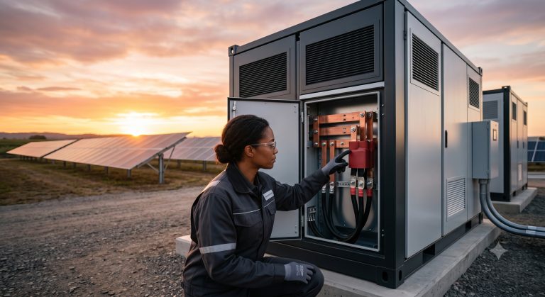
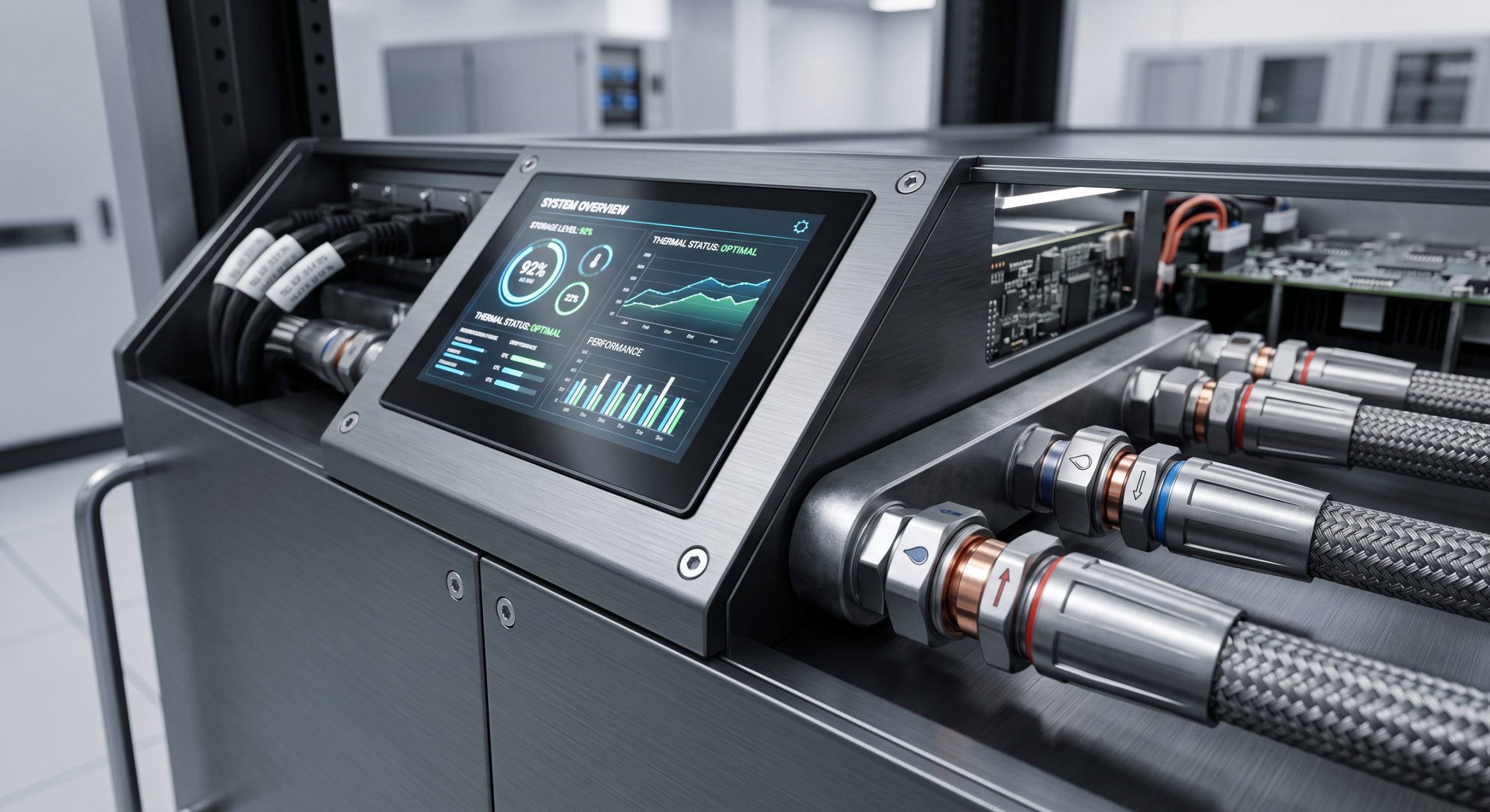
Although the Battery Management System (BMS) remains in a deep sleep state during transport and lifting, a pre-lift verification of the BMS communication harnesses and the liquid cooling quick-connect couplings is a critical prerequisite. The handling team must confirm that all external isolation valves for the thermal management circuit are fully closed to prevent fluid surge or cavitation within the cold plates during any minor tilting movements encountered during the rigging process. The BMS cell voltage balancing algorithm is inactive during the lift; however, the physical integrity of the cell monitoring harnesses must be visually inspected through the maintenance access ports. Any sign of abrasion, connector dislodgement, or structural deformation of the racking within the container necessitates an immediate halt to lifting operations and a formal engineering review to prevent potential internal short circuits or thermal runaway propagation post-commissioning.
KEY FEATURES
– Dedicated Four-Point Lifting Lugs: High-tensile steel lifting lugs are welded to the main structural frame at specified locations, each certified for a minimum Working Load Limit (WLL) of 12,500 kg, ensuring a balanced lift with a safety factor exceeding 5:1.
– Forklift Pocket Integration: The container base frame is equipped with reinforced fork pockets compliant with ISO 1496-1, allowing for safe handling via heavy-duty reach stackers with a minimum rated capacity of 40 tons.
– Center of Gravity Marking: High-visibility CoG decals are affixed to the exterior side panels, indicating the exact three-dimensional balance point of the fully populated Tier-1 LFP racking system, preventing uncontrolled pendulum motion during crane hoisting.
– Shock-Absorbing Base Pads: Elastomeric vibration isolation mounts are integrated between the internal battery racks and the container floor, mitigating dynamic shock loads encountered during road transport and lifting positioning.
– Sealed Cable Entry Interface: The lifting process necessitates no uncapping of the high-voltage DC busbar interface; the IP66-rated cable glands maintain environmental sealing integrity throughout the mechanical handling phase.
VERIFIED SPECS
The structural integrity of the container is engineered to meet the rigorous demands of international logistics. The corner fittings conform to the ISO 1161 standard, allowing for twist-lock engagement with standard spreader beams. The dynamic load rating during lifting is validated against a 2G vertical and 1G horizontal acceleration profile, ensuring the internal cell modules, busbars, and liquid cooling piping remain within mechanical tolerance. The container’s total gross weight, including the Tier-1 LFP modules and the integrated thermal management skid, defines the required crane tonnage and rigging gear capacity. All lifting equipment (slings, shackles, spreader bars) must be certified and inspected within the last 6 months, with a documented color-code system in place at the site.
| Parameter | Specification |
|---|---|
| Container Gross Weight | Up to 42,000 kg (fully populated with Tier-1 LFP) |
| Lifting Point WLL | 12,500 kg per corner casting (ISO 1161 compliant) |
| Center of Gravity | Marked on exterior; typically located at 1/3 height from base |
| Required Crane Capacity | Minimum 50-ton lifting capacity at required radius |
| Liquid Cooling Loop State | Isolation valves closed; pressure maintained at 1.5 bar N2 blanket |
| Pad Load Bearing | Minimum 15,000 kg/m² uniform load capacity |
| Settling Period Pre-Commissioning | 2 hours before loop pressurization |
| Corner Bolt Torque | 450 Nm (M24 high-tensile) |
LOCAL O&M MAINTENANCE LOGIC
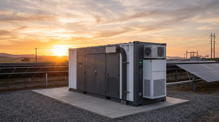
Upon final positioning on the outdoor pad, the lifting team must execute a controlled descent, ensuring the container is lowered vertically without any lateral drag on the footings. Once the container is seated, the corner castings must be secured to the foundation using M24 high-tensile bolts torqued to 450 Nm. The post-lift O&M protocol dictates that the container be allowed to settle for a period of 2 hours prior to re-pressurizing the liquid cooling loop. This settling period allows the internal fluid to return to the sump and any entrapped air to migrate to the automatic air vents. Following the stabilization period, a low-pressure leak test of all external fluid couplings must be conducted before the main BMS wake-up sequence is initiated. Any deviation from the specified torque values or fluid pressures must be logged in the commissioning report and rectified prior to energization.
📥 Download Technical Specification
Click the button below to view or download the full official PDF datasheet.