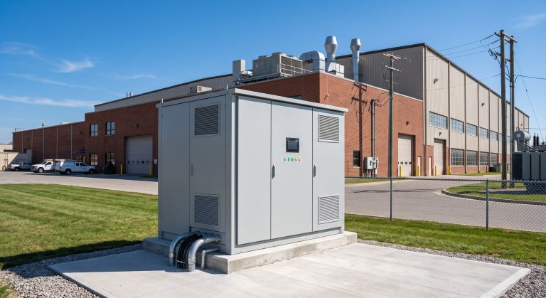
Introduction: The Architectural Imperative in Commercial Energy Storage
As global commercial and industrial (C&I) electricity prices continue their volatile upward trajectory—with peak demand charges in regions like Western Europe and North America exceeding $25/kW—the energy storage system architecture has evolved from a simple battery backup to a sophisticated, multi-layered asset. For B2B stakeholders, understanding the architectural blueprint is no longer optional; it is the foundation of Levelized Cost of Energy (LCOE) optimization and grid resilience. A poorly architected system can degrade 30% faster than its rated cycle life, while a well-designed architecture can unlock demand response revenue streams and extend operational longevity beyond 15 years.
This technical deep dive dissects the modern energy storage system architecture, moving from the cell level to the cloud-based Energy Management System (EMS). We will explore how Tier-1 LFP (Lithium Iron Phosphate) chemistry, advanced BMS (Battery Management System) topologies, and liquid cooling thermal management converge to deliver round-trip efficiency (RTE) exceeding 90% in real-world C&I deployments.
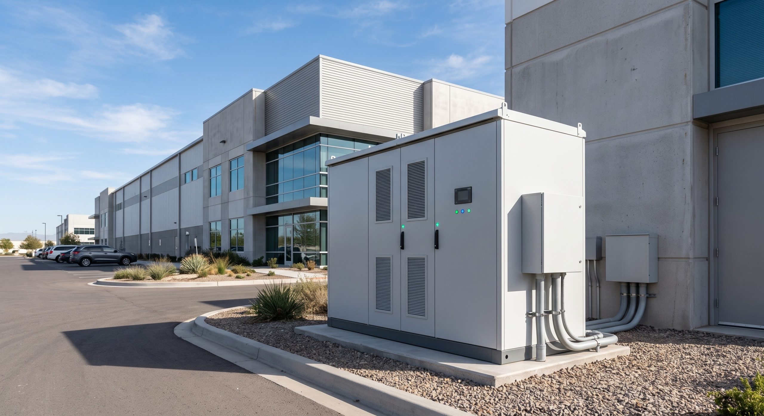
Core Architecture: PCS, BMS, and the DC/AC Coupling Topology
The Bi-Directional Power Conversion System (PCS)
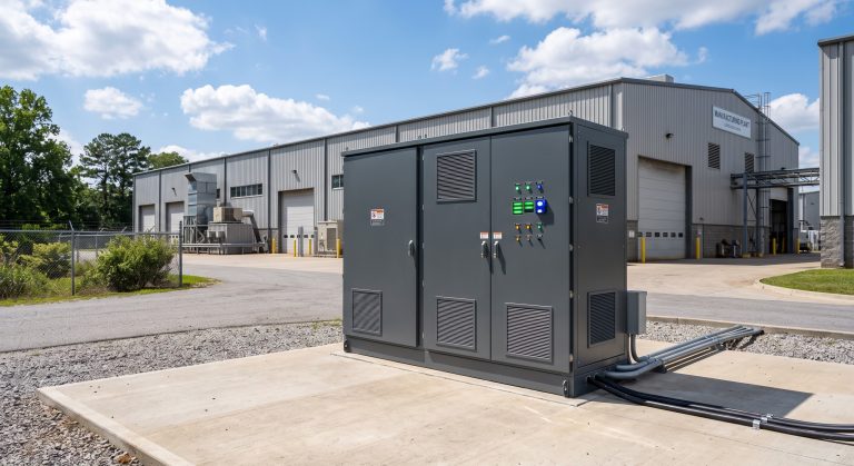
At the heart of any energy storage system architecture lies the PCS (Power Conversion System). Unlike traditional inverters, the PCS must manage bi-directional power flow with millisecond-level precision. In C&I applications, grid-tied PCS units typically operate at efficiencies of 98.5% (peak) and 97.5% (European weighted). The architecture must account for AC coupling (retrofits) versus DC coupling (new PV+Storage builds). DC-coupled architectures minimize conversion losses by sharing a common DC bus, improving overall RTE by 2-4% compared to AC-coupled counterparts.
Battery Management System (BMS) Hierarchy
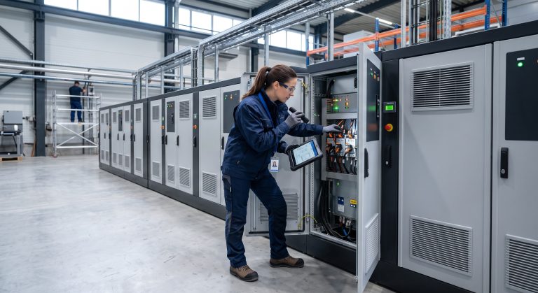
A robust BMS is not a single component but a three-tier architecture: BMU (Battery Monitoring Unit) at the module level, BCU (Battery Control Unit) at the rack level, and MBMS (Master BMS) at the container level. This hierarchy ensures cell balancing within ±10mV, critical for preventing premature degradation. Advanced BMS algorithms now employ State of Charge (SoC) and State of Health (SoH) estimation using Kalman filters, achieving accuracy within 3% even under dynamic load profiles.
Thermal Control: Liquid Cooling vs. Air Cooling
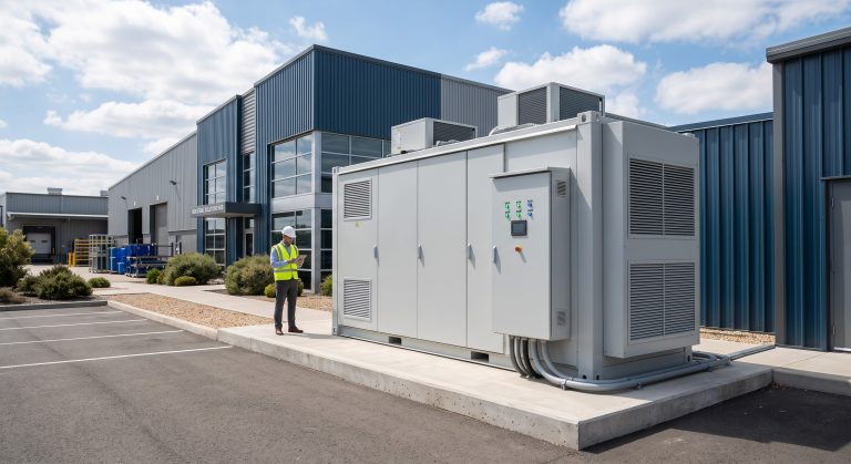
The choice of thermal management defines the architectural footprint. Liquid cooling maintains cell temperature differentials within ±2°C, compared to ±5-8°C for air cooling. This precision directly impacts cycle life: a 5°C reduction in average operating temperature can extend LFP cell life by 20-30%. For high-density C&I cabinets (e.g., 200-500 kWh), liquid cooling is the architectural standard, enabling 2C continuous discharge rates without thermal derating.
Technical Specifications: The Architectural Ledger
The following table outlines the critical architectural parameters for a Tier-1 215 kWh C&I energy storage system. These metrics are derived from IEC 62619 and UL 9540 testing protocols.
| Key Parameter | Technical Specification |
|---|---|
| Battery Chemistry | Tier-1 LFP (Lithium Iron Phosphate) |
| Nominal System Capacity | 215 kWh (expandable to 1.2 MWh) |
| Cycle Life | >8,000 cycles @ 90% DoD, 25°C |
| Round-Trip Efficiency (RTE) | ≥92% (DC-DC), ≥90% (AC-AC) |
| Depth of Discharge (DoD) | 95% maximum, 90% recommended |
| Thermal Management | Liquid Cooling (±2°C cell differential) |
| PCS Topology | Bi-directional, 3-level NPC, SiC-ready |
| Communication Protocol | Modbus TCP/IP, CAN 2.0B, IEC 61850 |
| Certifications | IEC 62619, UL 9540, CE, UN38.3 |
| Operating Temperature | -20°C to +55°C (derating above 45°C) |
| Fire Suppression | Aerosol + Perfluorohexanone (Novec 1230) |
| Grid Support Functions | Peak Shaving, Frequency Regulation, VPP Ready |
Commercial ROI & Grid Support: EMS Dispatch and Demand Response
Smart EMS Dispatch Logic
The EMS is the brain of the architecture. In a C&I setting, the EMS must execute peak shaving by forecasting load curves using machine learning. For a facility with a 500 kW peak demand, a 215 kWh system with 90% DoD can shave 150-200 kW of peak load, yielding annual savings of $15,000-$25,000 depending on utility tariffs. The EMS also manages demand response events, automatically bidding capacity into ancillary service markets (e.g., frequency regulation) with response times under 200 ms.
Round-Trip Efficiency (RTE) and LCOE Impact
RTE is the single most critical metric for LCOE. A system with 92% RTE versus 88% RTE delivers a 4.5% lower LCOE over a 10-year horizon. Architectural choices—such as using SiC (Silicon Carbide) semiconductors in the PCS and optimizing DC busbar resistance—directly influence this metric. UL 9540 certified systems often include RTE verification at 100% and 50% load points to ensure real-world performance.
Deployment Scenarios: From Industrial Parks to EV Supercharging
Industrial Park Micro-Grids
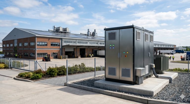
In industrial parks, energy storage system architecture must support parallel cabinet expansion for scalability from 215 kWh to MWh-scale. The architecture employs inter-cabinet busbar linkage with CAN bus or Ethernet communication for synchronized dispatch. This modularity allows facilities to defer CapEx, adding capacity as production lines expand.
PV-Storage-Charging (PSC) Integration
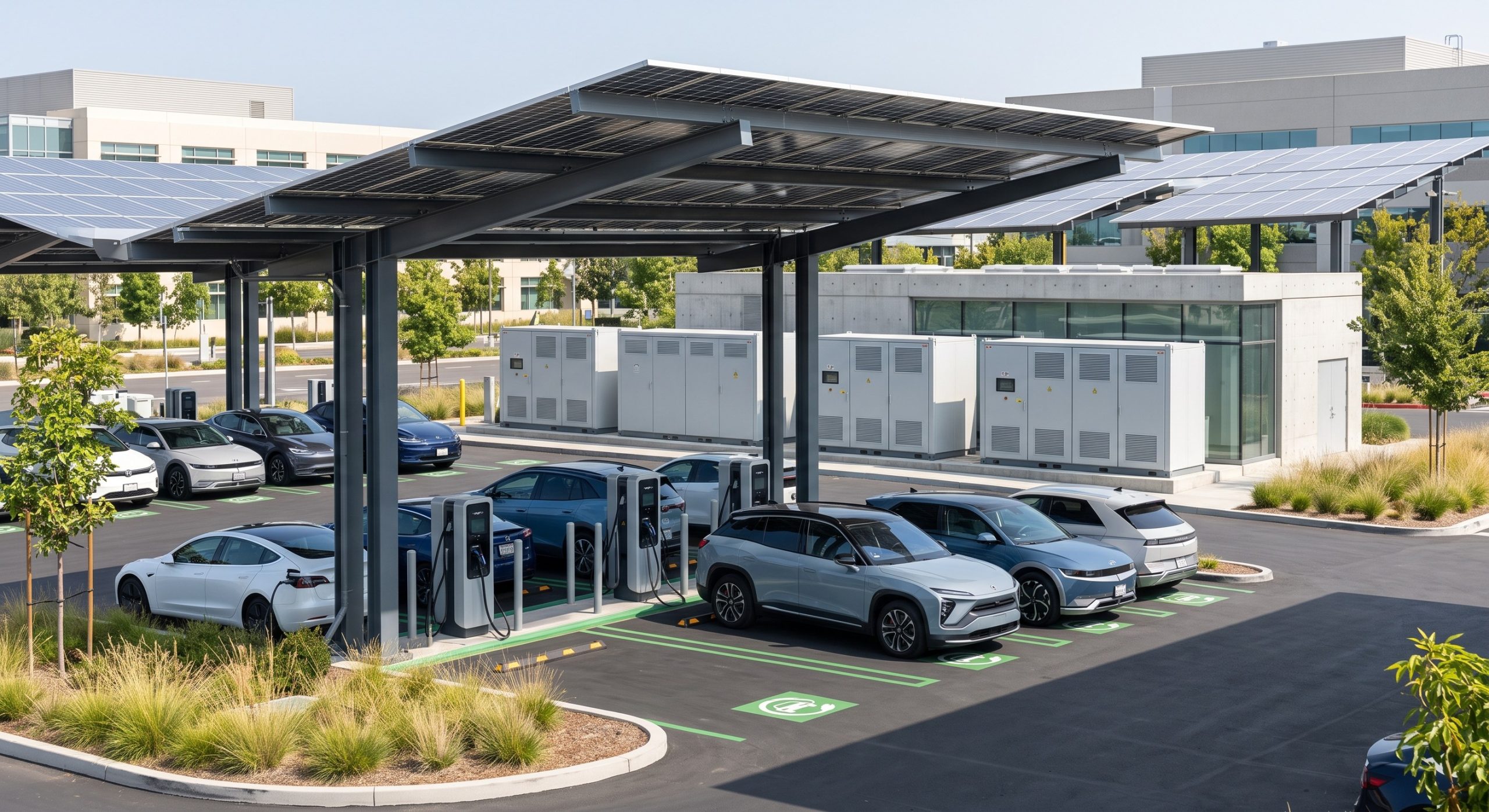
The most advanced deployment scenario integrates PV canopies, BESS, and EV superchargers. Here, the energy storage system architecture must manage DC-coupled solar inputs, AC-coupled grid ties, and 350 kW fast-charging loads. The EMS prioritizes solar self-consumption, then battery buffering, and finally grid import—reducing demand charges by up to 60% for charging hubs. UN38.3 certified transport and CE marking ensure global deployment compliance.
Conclusion: Architecting for the Next Decade of C&I Energy
The energy storage system architecture is a strategic asset, not a commodity. By specifying Tier-1 LFP cells with >8000 cycles, liquid cooling thermal management, and a BMS with UL 9540 and IEC 62619 certifications, B2B buyers can achieve LCOE below $0.08/kWh per cycle. As demand response markets mature and VPP (Virtual Power Plant) aggregation becomes mainstream, the architectural choices made today will determine whether a facility merely survives grid volatility or profits from it. The future belongs to systems that are not just stored energy, but intelligently dispatched, thermally optimized, and globally compliant.