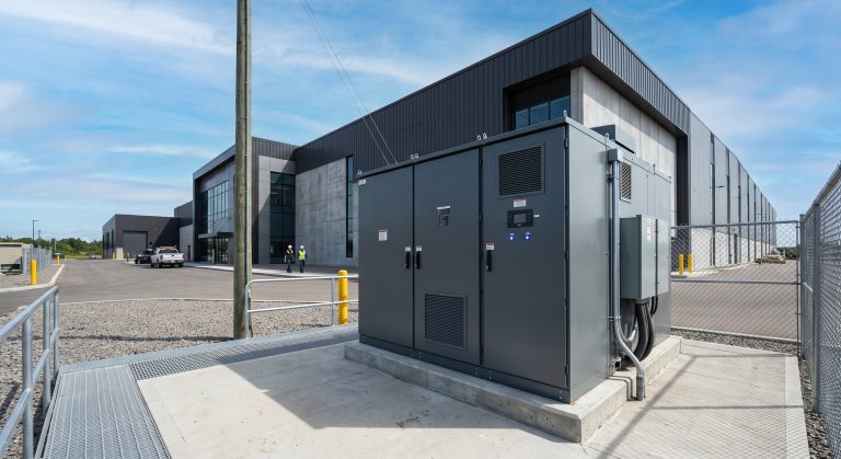
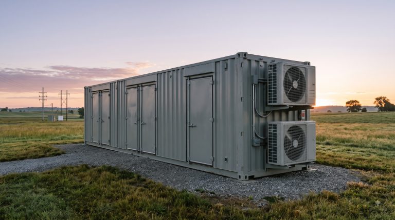
Overview
Dynamic power routing is the intelligent, real-time orchestration of energy flows between solar PV arrays, battery storage, the grid, and facility loads in an integrated solar-storage system. Unlike static dispatch schedules, dynamic routing continuously reads load profiles, tariff signals, state of charge (SoC), and grid conditions to decide—millisecond by millisecond—whether to charge, discharge, export, or island the system. For B2B plant engineers, EPCs, and procurement teams, understanding this mechanism is essential for sizing, ROI modeling, and post-sales O&M. Below are the most common pre-sales and post-sales questions we receive as a Tier-1 BESS technical support team.
Frequently Asked Questions
- Q1: How does dynamic power routing actually work in an integrated solar-storage system?
- Dynamic power routing works by using a bi-directional power conversion system (PCS) and an energy management system (EMS) to continuously arbitrate between four energy paths: solar generation, battery charge/discharge, grid import/export, and facility load. The EMS samples load demand, PV output, time-of-use tariffs, and battery SoC every 100–500 ms, then dispatches setpoints to the PCS so that solar power first serves loads, surplus solar charges the battery, and only excess energy is exported. When PV is insufficient, the battery discharges to shave peak demand before the grid is called upon. This closed-loop logic is what separates dynamic routing from simple net-metering or manual dispatch.
- Q2: What battery chemistry and cycle life should I specify for high-cycle dynamic routing applications?
- Tier-1 LFP (lithium iron phosphate) is the standard chemistry for high-cycle dynamic power routing, delivering 6,000–8,000 cycles at 80% depth of discharge (DoD) and 10–15 year design life. LFP is preferred over NMC for stationary BESS because of its superior thermal stability, lower degradation rate under partial state of charge, and lower cost per cycle. For a system cycling once per day, 6,000 cycles equates to roughly 16 years of operational life before reaching 80% state of health (SoH). Always request cell-level test data (e.g., IEC 62619 or UL 1973 reports) and confirm the warranty defines end-of-life capacity, not just cycle count.
- Q3: How does the cooling system support dynamic routing under high C-rate dispatch?
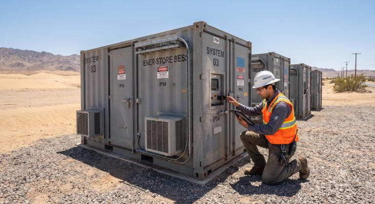
- Liquid cooling is essential for dynamic routing because high C-rate charge/discharge cycles generate concentrated heat that air cooling cannot remove evenly. A well-designed liquid cooling circuit maintains cell-to-cell temperature delta below 3°C and keeps the pack within a 15–35°C operating window, which directly preserves cycle life and prevents derating during peak shaving events. Plate-type or cold-plate liquid cooling with intelligent pump modulation responds to real-time C-rate and ambient temperature, cutting parasitic power consumption by 20–30% versus fixed-speed cooling. For outdoor enclosures, specify IP65+ ratings and anti-corrosion coatings if the site is coastal or industrial.
- Q4: Can dynamic power routing switch seamlessly between grid-tie and off-grid (islanding) mode?
- Yes. A BESS with dynamic power routing and a bi-directional PCS can transfer from grid-tie to off-grid mode in under 20 ms, well within the ride-through window of most industrial loads. The PCS forms a voltage and frequency reference for the islanded bus, while the EMS re-dispatches solar and battery to match the isolated load profile. For critical facilities, specify a static transfer switch (STS) or seamless transfer mechanism and verify the switchover time against your UPS and motor load tolerances. Note that true seamless islanding requires anti-islanding protection compliant with UL 1741 SB or equivalent grid codes.
- Q5: How is ROI calculated for dynamic power routing in peak shaving and demand response?
- ROI for dynamic power routing is calculated by summing peak demand reduction savings, time-of-use energy arbitrage, demand response program revenue, and avoided diesel or outage costs, then dividing by total installed cost. A typical C&I project achieves payback in 4–7 years when demand charges exceed $15/kW and the battery performs at least 300 cycles per year. Key inputs include your 15-minute interval load data, utility tariff structure, battery round-trip efficiency (88–92% for LFP + PCS), and degradation curve. Always model LCOE over 10 years rather than simple payback, because cycling depth and cooling parasitic loads materially affect lifetime cost per kWh.
- Q6: What BMS monitoring and inter-cell balancing protocols are used in dynamic routing systems?
- Dynamic power routing relies on an active BMS that reports cell voltage, temperature, SoC, SoH, and fault status to the EMS over CAN bus or Modbus TCP, typically at 1–10 Hz. Active balancing transfers charge between cells to keep voltage spread under 20–30 mV, which is critical when the system is cycling aggressively for peak shaving. The BMS must also enforce protection thresholds—over-voltage, under-voltage, over-temperature, and over-current—and communicate state-of-charge limits to the PCS so dispatch never pushes cells beyond safe operating windows. For post-sales support, confirm remote firmware update capability and API access for SCADA integration.
- Q7: What fire safety and thermal runaway prevention measures are required for integrated solar-storage systems?
- Multi-tier fire safety for BESS includes cell-level gas and smoke detection, pack-level aerosol or clean-agent suppression, cabinet-level deflagration venting, and system-level emergency stop and isolation. UL 9540 and UL 9540A test data should be requested to confirm that thermal runaway propagation is contained within a single module or unit. Liquid cooling with redundant temperature sensors and BMS-triggered contactor opening adds another layer of prevention. For indoor or containerized installations, integrate fire alarm dry contacts with the facility’s fire panel and ensure clearance distances meet NFPA 855 requirements.
- Q8: How scalable is dynamic power routing across parallel cabinets and larger microgrids?
- Dynamic power routing scales by paralleling battery cabinets on a shared DC busbar or AC bus, with the EMS aggregating all units into a single dispatchable resource. Modular designs allow incremental capacity additions from 100 kWh to 10+ MWh without replacing existing cabinets, provided the PCS and EMS support parallel operation and equal current sharing. For microgrids, the EMS can coordinate multiple PCS units, solar inverters, and generators under one optimization layer. Confirm that the parallel communication protocol (CAN or Ethernet) supports at least 16–32 units and that the EMS has a documented scalability limit before specifying a large deployment.