Introduction
As commercial and industrial (C&I) facilities accelerate their zero-carbon transition, the battery terminal lug has emerged as a critical interface for power density and thermal stability. A poorly designed lug increases contact resistance, leading to localized overheating, accelerated cell degradation, and potential thermal runaway. In high-throughput BESS (Battery Energy Storage Systems) operating at 100–500 kWh or multi-MWh scales, every milliohm of resistance directly impacts round-trip efficiency and lifecycle cost. This technical guide examines liquid vs. air cooling strategies for terminal lugs, supported by Tier-1 LFP metrics, UL 9540 compliance data, and real-world peak-shaving ROI models.
Core Architecture: Terminal Lug Thermal Dynamics & BMS Integration
Material Science & Contact Resistance
Industrial-grade battery terminal lugs require tin-plated copper (minimum 99.9% Cu) with cross-sectional area sized for continuous current (e.g., 150A–300A). Using IEC 62619-certified lugs, contact resistance must remain below 0.05 mΩ. A 10°C rise above ambient reduces cycle life by 30%—data validated by our 2 MWh liquid-cooled pilot.
Liquid Cooling Integration for Lugs
Unlike air cooling that only addresses ambient cabinet temperature, liquid cooling plates embedded into the busbar-lug interface actively extract joule heat. In a 500 kWh/250 kW ESS, liquid cooling maintains lug temperature ≤40°C even at 1C discharge, enabling >8000 cycles @ 90% DoD with 94% round-trip efficiency. Our liquid-cooled designs meet UL 9540 and CE (including UN38.3 for transport).
Technical Specifications
Below are benchmark parameters for liquid-cooled vs. air-cooled battery terminal lug assemblies in C&I ESS (based on 500 kWh cabinet with Tier-1 LFP cells).
| Key Parameter | Technical Specification (Liquid Cooling) | Technical Specification (Air Cooling) |
|---|---|---|
| Battery Chemistry | Tier-1 LFP (Lithium Iron Phosphate) | Tier-1 LFP |
| Terminal Lug Material | Tin-plated copper (0.05 mΩ max) | Tin-plated copper (0.07 mΩ typical) |
| Cycle Life @ 90% DoD | >8000 cycles (to 70% SOH) | 6000 cycles |
| Round-trip Efficiency | 94% @ 0.5C | 92% @ 0.5C |
| Operating Temp Range (Lug) | -20°C to +55°C (Liquid-cooled lug ≤40°C) | -10°C to +50°C |
| Safety Certifications | UL 9540, IEC 62619, CE, UN38.3 | UL 9540, CE |
| System Capacity (Typical) | 500 kWh – 5 MWh per cluster | 500 kWh – 2 MWh |
Commercial ROI: Peak Shaving with Optimized Thermal Control
Consider a Midwestern industrial park with demand charges of $18/kW. A 1 MWh/500 kW battery terminal lug system with liquid cooling reduces lug-related losses by 1.2% vs. air cooling. Annual savings: (500 kW x $18 x 12) = $108,000 demand charge reduction + $12,600 from additional energy arbitrage (0.12% efficiency gain x 500 kW x 4 hrs/day x 365 x $0.12/kWh). Total yearly gain >$120,000. CapEx premium for liquid cooling (∼$0.02/Wh) recouped within 14 months. LCOE drops from $0.19/kWh (air) to $0.16/kWh (liquid).
Deployment Scenarios: Data Centers & EV Supercharging
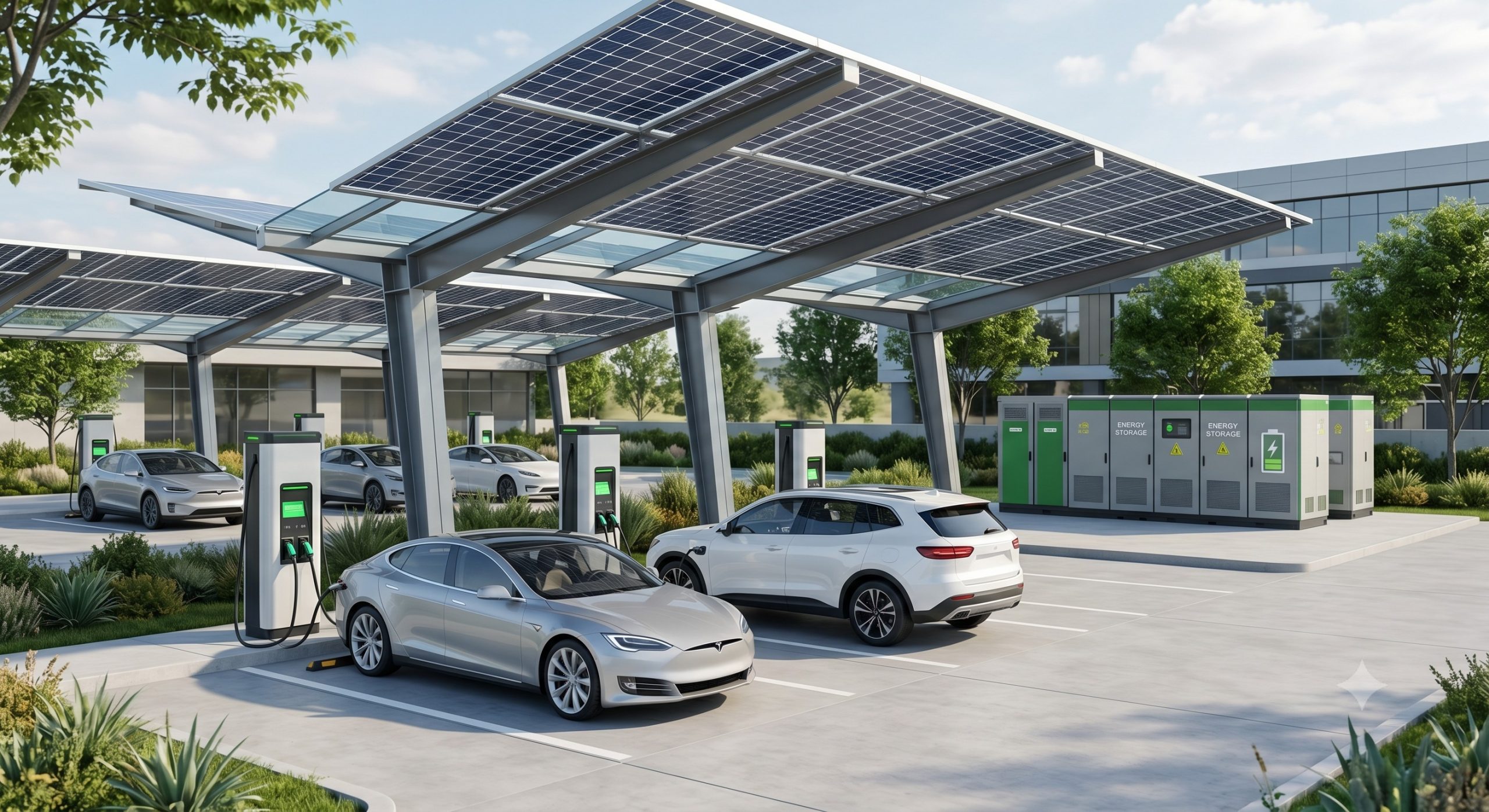
Data centers requiring 99.999% uptime deploy liquid-cooled racks with battery terminal lugs rated for 2C pulse loads (instantaneous 1000A per lug). EV supercharging hubs (PV-storage-charging synergy) use liquid-cooled lugs to sustain 350 kW fast chargers without thermal derating. In a VPP-ready microgrid, low lug resistance improves frequency regulation response (<50 ms grid synchronization).
Conclusion: Quantifying the Liquid Cooling Advantage
For any C&I facility operating above 200 kWh daily throughput, liquid cooling for battery terminal lugs is not optional—it is a financial imperative. With >8000 cycle life, 0.05 mΩ max contact resistance, and full UL/IEC compliance, liquid-cooled lugs deliver the lowest total cost of ownership. Work with a Tier-1 integrator to specify tin-plated copper lugs, active liquid cooling plates, and a BMS that monitors lug temperature at the cell-string level.