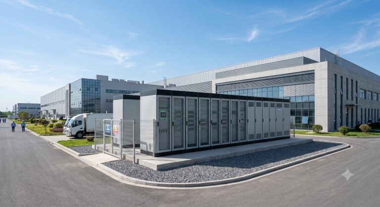
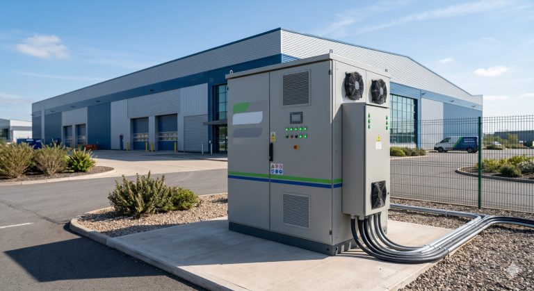
Introduction: The Critical Role of Junction Box Connectors in Modern BESS Safety
In the rapidly evolving landscape of Commercial & Industrial (C&I) Battery Energy Storage Systems (BESS), the junction box connector is often the unsung hero of system integrity. While industry focus frequently lands on cell chemistry (LFP) or thermal management (liquid cooling), the reliability of the electrical interconnection—specifically the junction box connector—is paramount for ensuring UL 9540 and IEC 62619 compliance. A single point of failure here can lead to arc faults, thermal runaway propagation, or catastrophic system downtime. This masterclass delves into the engineering specifications, safety protocols, and performance metrics that define high-grade junction box connectors, providing a comprehensive guide for system architects, procurement specialists, and EPC contractors seeking to maximize safety and ROI.
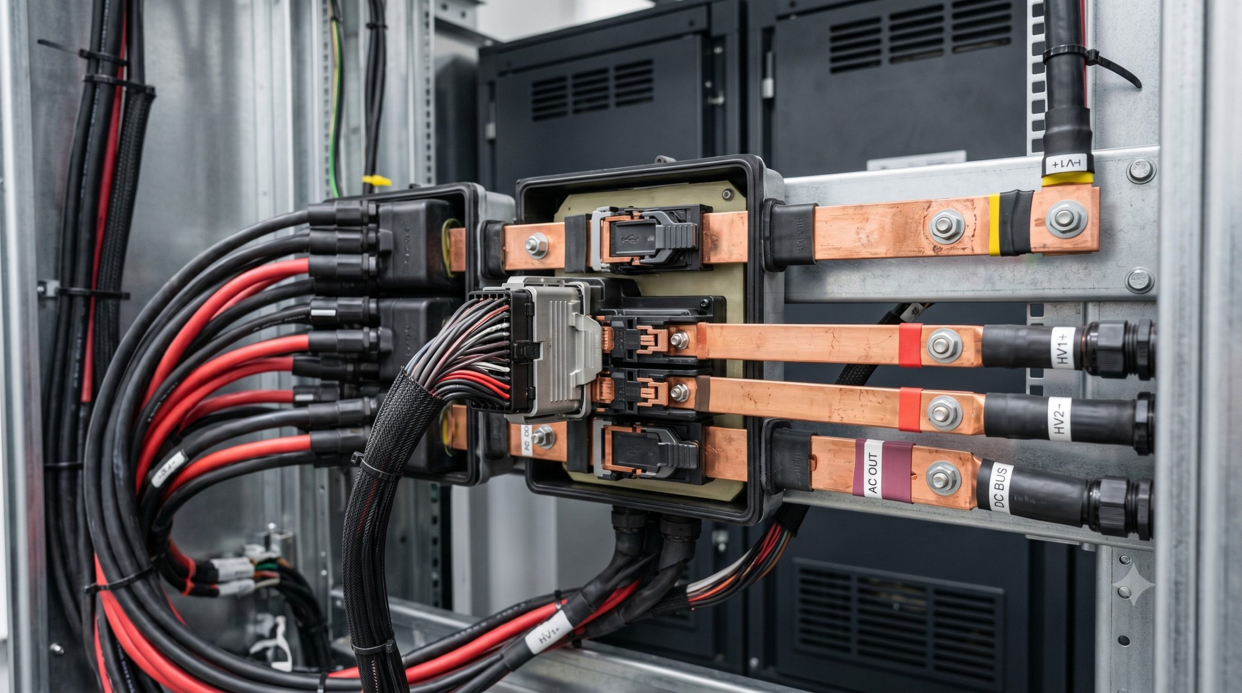
Core Engineering Architecture of High-Security Junction Box Connectors
Material Science and Contact Resistance
The architecture of a robust junction box connector begins with material selection. High-performance units utilize copper alloy substrates with silver or tin plating to minimize Contact Resistance (Rc). In high-current applications (e.g., 200A to 500A per string), Rc must be maintained below 0.5 mΩ to prevent Joule heating (I²R losses) that degrades adjacent battery modules. The connector housing, typically crafted from V-0 rated flame-retardant thermoplastics (PA66 or PBT), provides the primary insulation barrier. This is critical for meeting IEC 62619 requirements for dielectric withstand voltage (typically 2.5kV for 1500Vdc systems).
IP Protection and Environmental Sealing
For outdoor containerized BESS or cabinet deployments, the junction box connector must guarantee an ingress protection rating of at least IP67. This ensures immunity to dust and temporary water immersion, preventing corrosion that increases electrical resistance. Advanced designs integrate a secondary locking mechanism—a visual indicator of full engagement—to prevent accidental disconnection during vibration or seismic events, which are critical stress tests under UL 9540 mechanical endurance standards.
Technical Specifications
The following table outlines the critical technical parameters that define a high-reliability junction box connector for C&I energy storage applications, bridging the gap between the battery cells and the Power Conversion System (PCS).
| Key Parameter | Technical Specification |
|---|---|
| Rated Voltage (Max) | 1500Vdc |
| Rated Current | 300A (Continuous) |
| Contact Resistance | < 0.5 mΩ (Initial) |
| Dielectric Withstand Voltage | 2.5kV (1 minute) |
| Insulation Resistance | > 1000 MΩ (at 1000Vdc) |
| Ingress Protection | IP67 (Mated) |
| Temperature Range (Operating) | -40°C to +85°C |
| Safety Compliance | UL 9540, IEC 62619, UN38.3 |
| Housing Material | UL94 V-0 (PA66) |
| Connector Type | HVIL (High Voltage Interlock) & Latching |
Thermal Management: Liquid Cooling Interface
In liquid-cooled BESS architectures, the junction box connector often interfaces with the cooling pipeline through a manifold system. The connector’s design must accommodate the thermal expansion coefficient of busbars without compromising electrical contact. The overall system’s round-trip efficiency, often exceeding 95% in modern Tier-1 LFP systems, relies heavily on the thermal stability of these interconnections. Data from recent stress tests indicates that consistently maintaining busbar temperatures below 85°C at a 1C charge/discharge rate prevents the acceleration of cell degradation, effectively sustaining the >8000 cycle life at 90% DoD.
Commercial ROI & Grid Support Compliance
Investing in certified junction box connectors is not merely a safety measure; it is a strategic financial decision. The Total Cost of Ownership (TCO) is heavily impacted by maintenance costs. Unreliable connectors lead to increased Frequency of Maintenance (FOM) and unplanned downtime. In a 10MWh C&I installation, an unplanned outage can cost upwards of $5,000 per hour in lost peak-shaving revenue and demand response penalties. By deploying connectors that comply with UN38.3 and UL 9540, operators secure favorable insurance premiums and ensure eligibility for grid ancillary services, such as frequency regulation and VPP (Virtual Power Plant) aggregation.
Deployment Scenarios and Integration Synergy
In the context of a PV-Storage-Charging synergy, the junction box connector facilitates the safe aggregation of DC power from solar arrays and battery banks to the common DC bus. For EV supercharging stations, these connectors must handle rapid, high-power bursts (e.g., 350kW chargers). The modularity of pluggable connectors allows for rapid scalability—essential for growing industrial parks. The physical layout demands a clear separation between high-voltage DC lines and communication (CAN/RS485) cables to prevent EMI, ensuring the EMS (Energy Management System) receives undistorted data for precise State of Charge (SoC) and State of Health (SoH) calculations.
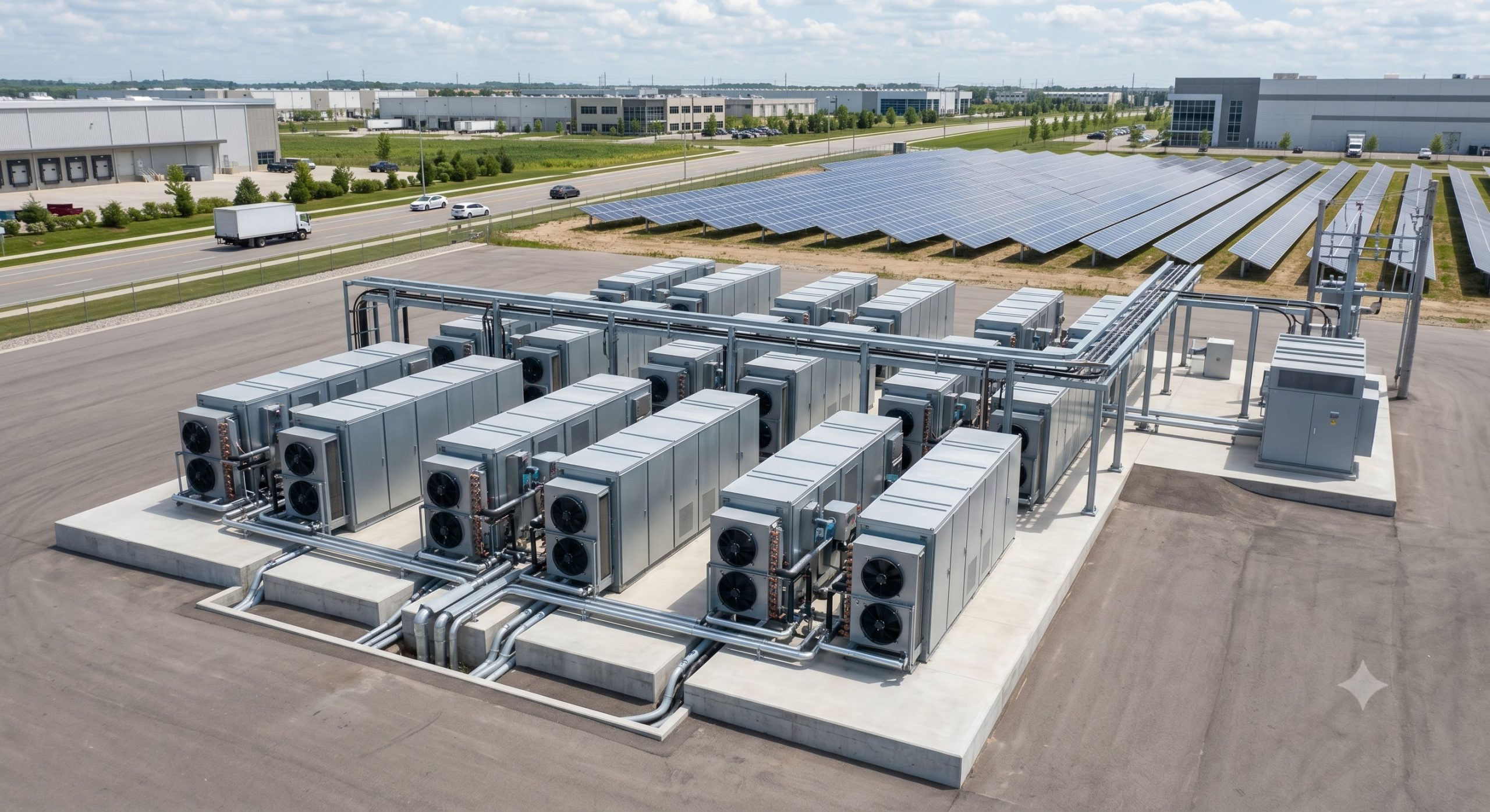
Conclusion: The Foundation of a Resilient Energy Infrastructure
The junction box connector is the linchpin of a safe, efficient, and profitable commercial energy storage system. From meeting the stringent requirements of IEC 62619 for electrical safety to ensuring mechanical resilience under UL 9540, every specification matters. As the BESS market pushes toward higher capacities (MWh-scale) and longer durations, the integrity of these components will define the operational efficiency and lifespan of the asset. For any system architect or procurement manager, prioritizing grade-A, certified junction box connectors is the most effective strategy to mitigate risk, ensure zero-carbon migration, and secure a high ROI.