Overview
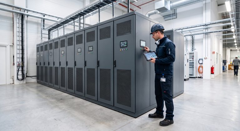
Pin terminals are critical components in high-voltage Battery Energy Storage Systems (BESS), ensuring reliable electrical conductivity between battery modules, busbars, and the Power Conversion System (PCS). This FAQ addresses the most technically demanding B2B questions regarding pin terminal integration, safety, performance, and lifecycle economics—designed to help plant engineers, procurement managers, and system integrators make informed decisions.
Frequently Asked Questions
- Q1: What is the maximum cycle life and depth of discharge (DoD) for a BESS using pin terminal connections?
- The standard cycle life of a LFP-based BESS with pin terminal interconnects is 6,000 to 8,000 cycles at 90% DoD, extendable to 10,000+ cycles at 80% DoD. Pin terminal contact resistance (typically <0.1 mΩ) directly influences cycle life by minimizing heat generation and voltage drop. Lower contact resistance reduces cell balancing frequency, preserving active material integrity. For maximum longevity, specify tin-plated or silver-plated copper pin terminals with a retention force ≥50N per contact.
- Q2: How does active BMS monitoring interface with pin terminal connections?
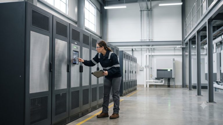
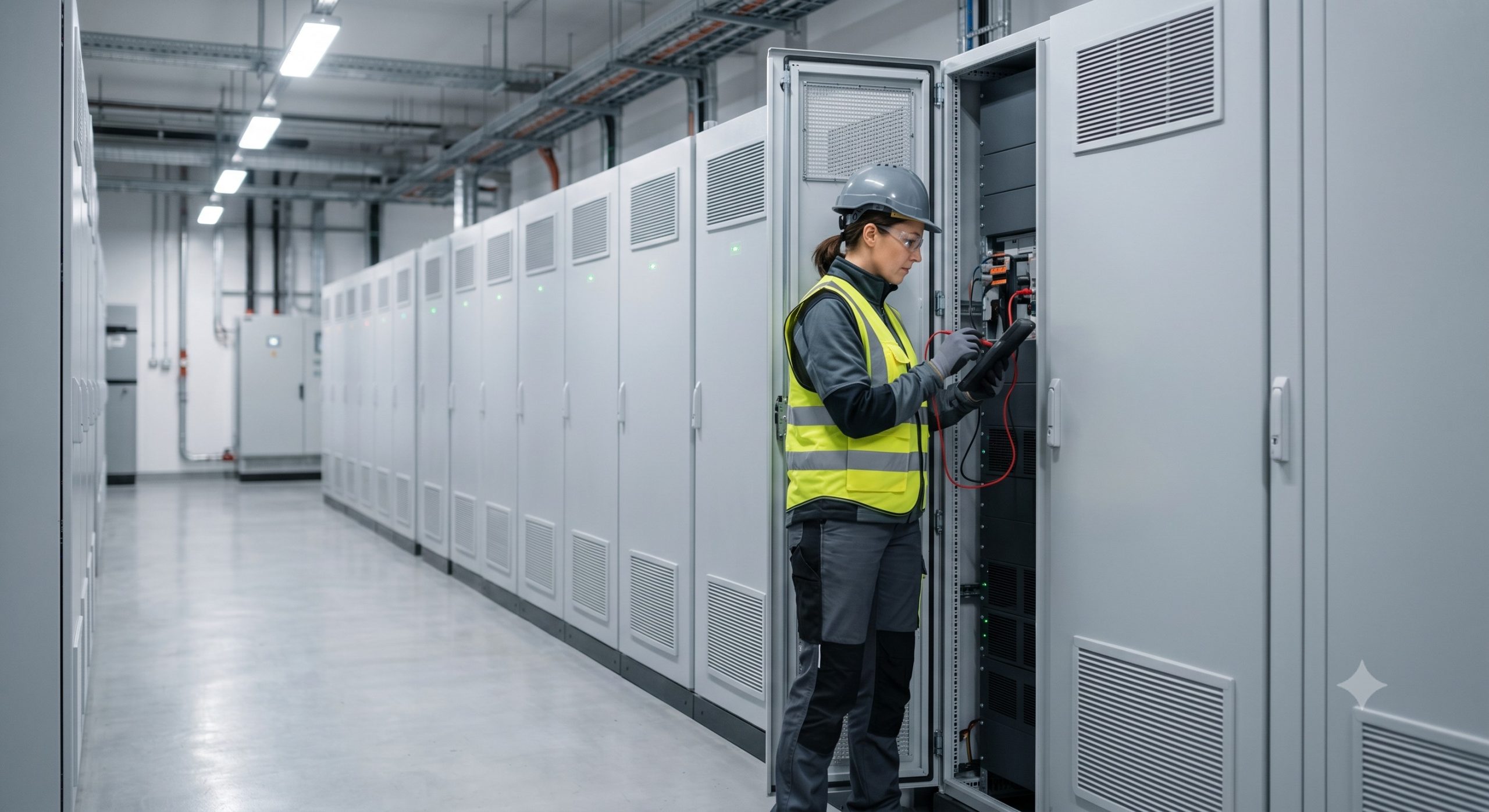
- Active BMS monitoring integrates via dedicated sensing wires crimped or soldered to secondary pin terminal ports, enabling real-time per-cell voltage and temperature tracking. The BMS measures voltage drop across each pin terminal pair to detect micro-ohms increases that indicate corrosion or loosening. In Tier-1 BESS designs, pin terminals incorporate integrated thermistor wells or JST-style auxiliary pins that transmit data to the BMS every 100–200ms. This allows pre-failure warnings when contact resistance rises above 0.5 mΩ, preventing thermal events.
- Q3: What liquid cooling circuitry is compatible with high-current pin terminals?
- High-current pin terminals (rated 200A–600A) require cold plate integration with electrically isolated coolant passages—typically aluminum or stainless steel cold plates with deionized water/glycol mixtures. The pin terminal housing must be IP67-rated against coolant leakage, with compression seals (EPDM or silicone) around each terminal entry point. For 1500V DC systems, cooling plates must maintain surface temperatures below 65°C at pin terminal mating points. Industry best practice: Use indirect cooling where pin terminal blocks are bolted to cold plates via thermally conductive but electrically insulating pads (7–10 W/m·K).
- Q4: What fire safety and thermal runaway prevention features apply to pin terminal connections?
- Pin terminal fire safety is achieved through three layers: (1) Arc-flame-retardant housings made of V-0 rated PA66 or PBT plastic; (2) Touch-proof IP2XB finger-safe covers that prevent accidental bridging; (3) Passive melt fuses integrated into terminal blocks that open at 140–160°C to interrupt current before thermal runaway spreads. Additionally, UL 9540A-compliant BESS systems require pin terminals with clearance/creepage distances ≥12mm for 1500V systems. Early detection via thermal cameras or fiber-optic temperature sensors placed every 2–3 pin terminal blocks provides active prevention.
- Q5: Can pin terminal-based BESS be configured for both grid-tie and off-grid islanding?
- Yes, pin terminal interconnects support seamless grid-tie and off-grid islanding when paired with a bi-directional PCS equipped with anti-islanding protection (IEEE 1547 compliant). The critical requirement is that all pin terminals must be rated for the higher transient currents during islanding reconnection—typically 2x nominal current for 10 seconds. For automatic transfer switching (ATS), pin terminal contact materials must withstand micro-arcing; specify silver-nickel or silver-tin-oxide contacts for systems switching >500 cycles/year. Off-grid configurations also demand pin terminal vibration resistance (IEC 60068-2-6: 5g, 10–500Hz) since no utility grid stabilizes frequency.
- Q6: How scalable is a pin terminal BESS from 100 kWh to 10 MWh using parallel cabinet connectivity?
- Pin terminal architectures enable modular scaling via custom DC busbars that parallel up to 32 cabinets without re-engineering. Each cabinet (typically 100–500 kWh) uses primary pin terminals rated 400A/1500V to connect to a common copper busbar (cross-section ≥ 120mm² per 100A). For 10 MWh systems, implement hierarchical busbar tiers: sub-busbars (2 MWh each) connected to a main busbar via high-force dual pin terminals (spring-loaded, maintaining contact even under thermal cycling). Maximum parallel cabinets is limited by short-circuit current protection—use DC-rated MCCBs with interrupting capacity ≥50kA at each pin terminal junction.
- Q7: What is the ROI calculation timeline for a pin terminal-based C&I BESS including O&M?
- The Levelized Cost of Storage (LCOE) for pin terminal BESS ranges from $0.08–0.12/kWh over a 10-year lifespan, yielding ROI within 3–5 years for peak shaving and arbitrage. Calculate ROI using: (Annual energy arbitrage revenue + demand charge reduction + incentive payments) ÷ (Total installed cost + 10-year O&M). Pin terminals reduce O&M by 30% compared to bolted connections because they provide tool-less disconnection for module replacement. Factor in $0.002–0.005/kWh for annual contact resistance testing and re-torquing. For a 1 MWh system with 2-cycle daily operation at $0.15/kWh arbitrage spread, annual revenue = $109,500; at $120,000 installed cost, payback = 4.4 years.