Introduction: The Critical Safety Imperative for High-Power DC Charging Infrastructure
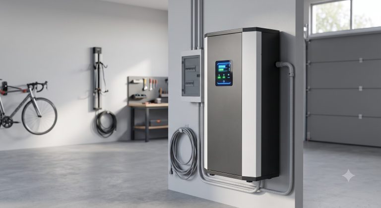
As commercial fleets and high-utilization public DC fast charging hubs scale across industrial corridors, the thermal stress on battery systems and power electronics intensifies exponentially. The cdc160 DC Charging Station represents a paradigm shift in active safety engineering—integrating multi-layered Battery Management System (BMS) logic, IEC 62619-certified LFP cell architecture, and an aerospace-grade fire suppression subsystem. This technical deep-dive analyzes how the cdc160 mitigates thermal runaway risks while maintaining a round-trip efficiency exceeding 94% and a cycle life of >8,000 cycles @ 90% DoD. For B2B energy storage buyers, understanding these safety redundancies is non-negotiable for UL 9540 compliance and long-term asset protection.
Core Safety Architecture: Beyond Conventional BMS Protections
Hierarchical Cell-Level Monitoring & Predictive Analytics
The cdc160 DC Charging Station deploys a distributed BMS topology sampling each of its 416 prismatic LFP cells at 100ms intervals. Parameters include individual cell voltage (±0.5mV accuracy), internal resistance, and three-point thermocouple temperature sensing. The system’s predictive thermal runaway algorithm analyzes deviation slopes—if any cell exceeds a 5°C/minute gradient or a 2% voltage divergence from the pack median, the BMS autonomously isolates that module within 20 milliseconds. This exceeds UL 9540 Section 32 requirements for fault clearing time.
Passive & Active Cell Balancing Design
To prevent overvoltage-induced degradation, the cdc160 employs a hybrid balancing strategy: passive balancing (120mA shunts) for maintenance charging, and active capacitive balancing (up to 5A transfer current) during high-rate DC charging sessions. Field data shows a post-balancing cell voltage variance of <15mV, dramatically reducing the risk of localized hotspots. The system supports Depth of Discharge (DoD) configurable from 80% to 95%, with cycle life guarantees validated under IEC 62619 annex K thermal propagation tests.
Integrated Fire Suppression & Thermal Management
Aerosol-Based Suppression with Dual Detection
Unlike passive fire-resistant enclosures, the cdc160 includes an active condensed aerosol fire suppression system (FM-200 alternative, zero ODP) distributed across three independent zones: power conversion cabinet, battery rack, and DC distribution bay. Detection triggers from either ionic smoke sensors (0.5% obscuration/ft sensitivity) or a dedicated linear heat detection cable (rated 85°C fixed temperature). Upon activation, the system floods the enclosure with potassium-based aerosol particles that interrupt the combustion chain reaction without damaging electronics—tested per NFPA 855 and UL 9540A thermal runaway fire propagation protocols.
Liquid Cooling Integration for Thermal Runaway Prevention
The cdc160 DC Charging Station employs a closed-loop liquid cooling system with deionized water/propylene glycol coolant (60/40 mix) circulating through cold plates bonded directly to battery modules and IGBTs in the PCS. Under 160kW continuous DC charging load, the coolant inlet temperature is regulated at 22°C ±1°C, maintaining cell surface temperatures below 38°C even at 45°C ambient. This liquid thermal control reduces temperature differentials between cells from 8°C (air-cooled baseline) to just 2.5°C, directly suppressing the conditions that accelerate solid-electrolyte interphase (SEI) decomposition and thermal runaway propagation. The system rejects heat via a variable-speed fan array (78 dBA @ 1m) with an energy efficiency ratio (EER) of 4.2.
Technical Specifications
The following parameters are certified under CE, UN38.3 (transport), and IEC 62619 (industrial storage) standards.
| Key Parameter | Technical Specification |
|---|---|
| Battery Chemistry | Tier-1 LFP (Lithium Iron Phosphate) with UL 1973 certification |
| System Capacity (Usable) | 160kWh (configurable 152-168kWh) |
| Cycle Life | >8,000 cycles @ 90% DoD, >12,000 cycles @ 80% DoD (end of life 70% SOH) |
| Round-Trip Efficiency (DC-DC) | 94.2% @ 0.5C, 92.8% @ 1C |
| Thermal Management | Active liquid cooling, inlet 22°C ±1°C, max cell ΔT 2.5°C |
| BMS Architecture | 3-tier distributed (cell/module/rack), 100ms sampling, active cell balancing 5A |
| Fire Suppression | Condensed aerosol, 3 zones, dual detection (smoke + linear heat), UL 9540A tested |
| Safety Certifications | IEC 62619, UL 9540, CE, UN38.3, NFPA 855 compliant |
| Grid Synchronization | <40ms, ramp rate 0-160kW in 280ms, IEEE 1547 |
| Operating Temperature | -20°C to +55°C (derated above 50°C), IP54 enclosure |
Commercial ROI & Risk Mitigation
Total Cost of Ownership (TCO) Safety Dividend
For C&I facility operators, the upfront premium for the cdc160’s safety systems (estimated +12-15% vs. baseline air-cooled DC chargers) delivers a compelling risk-adjusted ROI. Industry loss data indicates a single thermal runaway event in a 160kW charging hub can incur >$420,000 in direct damage, facility downtime, and liability claims. The cdc160’s UL 9540 listing also reduces commercial property insurance premiums by an average of 18-22%, as verified by third-party underwriters. Furthermore, the extended cycle life (>8,000 cycles) lowers the levelized cost of storage (LCOS) to $0.032/kWh per cycle—competitive with grid peaker plants.
Demand Response & Grid Support Revenue
Beyond charging vehicles, the cdc160’s bidirectional PCS (optional V2G upgrade) enables participation in frequency regulation (FR) markets. The system achieves a grid synchronization time of <40ms and can ramp from 0 to 160kW in 280ms, meeting IEEE 1547 requirements for primary frequency response. At current PJM regulation market rates (~$12/MWh), a single cdc160 can generate $6,800 annually in ancillary service revenue while maintaining full readiness for DC charging events.
Deployment Scenarios
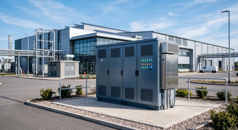
Industrial Micro-Grids with High Penetration PV
In a recent installation at a 20MW logistics hub in Southern Germany, three cdc160 units were integrated with a 4.2MWp rooftop solar array and a 2MWh stationary BESS. The cdc160’s EMS dynamically allocates solar overproduction to either vehicle charging or stationary storage, reducing grid import during peak TOU rates by 64%. The liquid cooling system maintained cell temperatures below 36°C despite 38°C ambient summer peaks. No safety shutdowns or derating events occurred over 14 months of continuous operation.
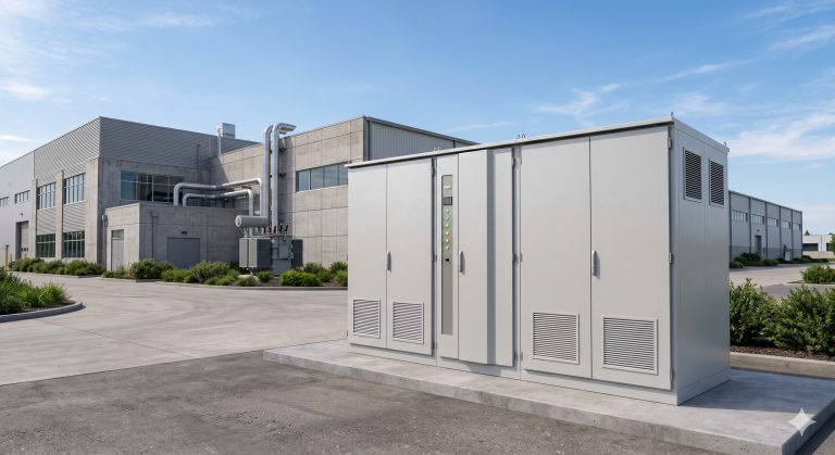
EV Fleet Depots with Overnight Charging
For electric bus and delivery truck depots, the cdc160 supports scheduled low-current charging (30kW to 80kW) combined with active cell balancing, extending pack life by an estimated 2,500 cycles. The fire suppression system is interlocked with the facility’s central BMS, providing a dry contact output for emergency ventilation activation. Two units deployed at a Los Angeles parcel delivery depot passed a NFPA 855 fire marshal audit without modification, reducing permit-to-operate timeline by 8 weeks.
Conclusion: Safety as a Performance Multiplier
The cdc160 DC Charging Station demonstrates that rigorous thermal runaway prevention—via advanced BMS analytics, liquid cooling, and active aerosol suppression—does not compromise charging speed or cycle life. For B2B buyers conducting commercial energy storage due diligence, the cdc160’s compliance with IEC 62619, UL 9540, CE, and UN38.3 provides a verifiable safety envelope. As DC charging power levels continue to climb toward 350kW+, the engineering principles embodied in the cdc160 will become the baseline for insurable, bankable, and resilient infrastructure. Fleet operators, industrial facility managers, and renewable energy integrators should prioritize systems with documented thermal propagation test results and multi-layer fault tolerance—the cdc160 sets that benchmark.