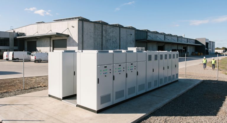
Introduction: The Business Case for Industrial-Scale Storage
For C&I enterprises, the challenge of rising grid instability, surging demand charges, and mandatory decarbonization targets is pushing energy infrastructure to a breaking point. Megawatt-level energy storage systems (MW-class BESS) are emerging as the definitive solution for facilities requiring robust backup power, peak load reduction, and direct participation in ancillary service markets. Unlike smaller commercial units, MW-scale systems are engineered for high-throughput cycling, long-duration discharge, and seamless integration with on-site renewables. This guide provides a system architect’s perspective on sourcing, evaluating, and deploying megawatt-level energy storage, from core battery chemistry and safety certifications to the financial modeling of Levelized Cost of Storage (LCOE) and Demand Response (DR) revenue streams. We will dissect the critical components, including Liquid Cooling PCS integration, BMS (Battery Management System) topology, and compliance with IEC 62619 and UL 9540, ensuring procurement managers and engineers have a definitive technical reference.
Core Architecture & Battery Management in MW-Class ESS
Tier-1 LFP Cell Chemistry and Configuration
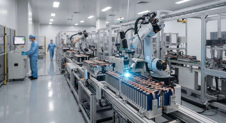
The foundation of any high-reliability megawatt-level energy storage system is the battery cell. Premium Tier-1 suppliers are exclusively utilizing prismatic LFP (Lithium Iron Phosphate) cells. LFP’s inherent thermal stability and cobalt-free composition make it superior for high-capacity configurations. A typical MW-scale system, such as a 2.5 MW / 5 MWh cabinet, consists of hundreds of cells arranged in a series-parallel matrix to deliver nominal DC voltages typically ranging from 800V to 1500V. This high-voltage architecture reduces current load, allowing for smaller cable cross-sections and higher Round-trip efficiency (RTE).
Advanced BMS Topology and Cell Balancing
A distributed, multi-layer Battery Management System (BMS) is non-negotiable for MW-scale deployments. The BMS must actively monitor voltage, temperature, and state of charge (SoC) at the cell, module, and rack levels. To maximize the >8000 cycle lifespan at 90% DoD, the BMS uses passive or active balancing algorithms. Active balancing is increasingly preferred for large systems as it redistributes energy during discharge and charge, preventing individual cells from reaching overcharge or deep discharge limits. This precision is vital for maintaining uniform degradation across the entire 5+ MWh array, ensuring the system meets warranty performance guarantees.
PCS and Liquid Cooling Synergy
The Power Conversion System (PCS) acts as the bidirectional brain, converting DC power from the batteries to AC for grid connection and vice versa. For megawatt-level energy storage, modular PCS units (e.g., 1MW, 2MW) are paralleled to achieve the desired power rating. A key engineering advancement is the integration of Liquid cooling for both the PCS and the battery racks. Liquid cooling (typically using a water-glycol mixture) offers superior thermal control compared to traditional air cooling, maintaining optimal operating temperatures (22°C-28°C) even under high C-rate (e.g., 0.5C to 1C) charging and discharging. This thermal management enhancement is critical for preventing derating, improving RTE by up to 2-3%, and significantly prolonging cycle life. Efficiency metrics for modern liquid-cooled MW systems consistently exceed 97% at the PCS stage and >90% overall system RTE.
Technical Specifications: Performance and Compliance Benchmarks
When evaluating megawatt-level energy storage suppliers, procurement teams must validate core technical parameters against stringent international safety and performance standards. The following table outlines the baseline requirements for a Tier-1 compliant MW-ESS system.
| Key Parameter | Technical Specification |
|---|---|
| System Capacity | 2 MW / 5 MWh to 5 MW / 15 MWh (Standard Configurations) |
| Battery Chemistry | Tier-1 LFP (Lithium Iron Phosphate) Prismatic Cells |
| Round-trip Efficiency (RTE) | >90% (AC to AC, including PCS and thermal losses) |
| Cycle Life | >8000 cycles @ 90% DoD (Depth of Discharge) to 70% EOL |
| Thermal Management | Integrated Liquid Cooling System (Water-Glycol) with Active PCS Cooling |
| PCS Rating | Modular, 1 MW or 2 MW bi-directional inverters, peak efficiency >98% |
| Safety & Compliance | UL 9540, IEC 62619, UN38.3, CE, IEEE 1547 / VDE-AR-N 4110 |
| BMS Architecture | Distributed 3-tier (Cell Module, Rack, System) with Active Balancing |
| Response Time | < 20 ms for grid-forming mode; < 200 ms for full load dispatch |
| Operating Temp. Range | 0°C to +50°C (full power, derating above 45°C) |
| Enclosure Rating | IP54 / IP55 (Outdoor Containerized) |
Deep Dive into Safety and Grid Compliance
Compliance with UL 9540 is mandatory for deployment in North America, covering the entire energy storage system and ensuring electrical and fire safety. Furthermore, the cells themselves must pass UN38.3 for safe transport. For European and Asian markets, adherence to IEC 62619 (secondary cells and batteries for industrial applications) and IEC 62477 (PCS safety) is equally critical. An often-overlooked standard is IEEE 1547 or VDE-AR-N 4110 for grid interconnection; compliance with these ensures the megawatt-level energy storage system can perform functions like Frequency Regulation (FR) and voltage support without destabilizing the local grid.
Commercial ROI & Grid Support: Financial and Operational Benefits
The adoption of megawatt-level energy storage is driven by a clear Total Cost of Ownership (TCO) and ROI model. The primary revenue streams include Peak Shaving to reduce demand charges, which can constitute 30-50% of a facility’s electricity bill; arbitrage by purchasing energy during low-cost off-peak hours and discharging during high-cost peak periods; and participation in utility Demand Response programs. The Levelized Cost of Storage (LCOE) for a 5 MWh system with an 8000-cycle lifespan at 90% DoD (Depth of Discharge) is consistently dropping below $0.10/kWh, making it economically viable against grid prices in many regions. Furthermore, the system’s 2-3 MW output capacity allows it to act as a reliable backup, replacing or reducing dependency on diesel generators (gensets) during grid outages. This not only provides a fast return on investment (typically 3-5 years) but also enhances corporate ESG ratings by reducing Scope 2 emissions.
Deployment Scenarios for MW-Class BESS
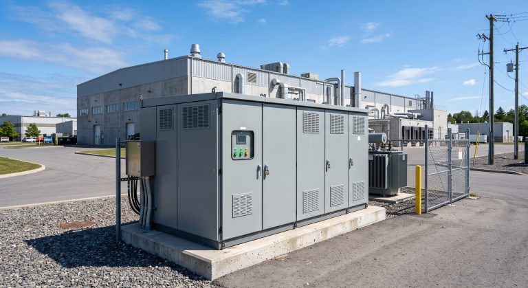
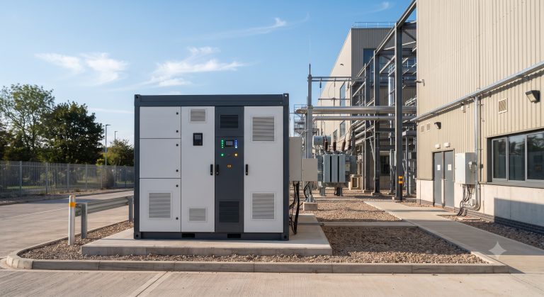
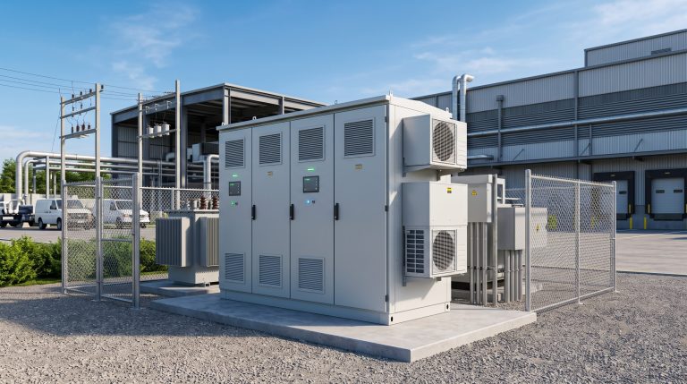
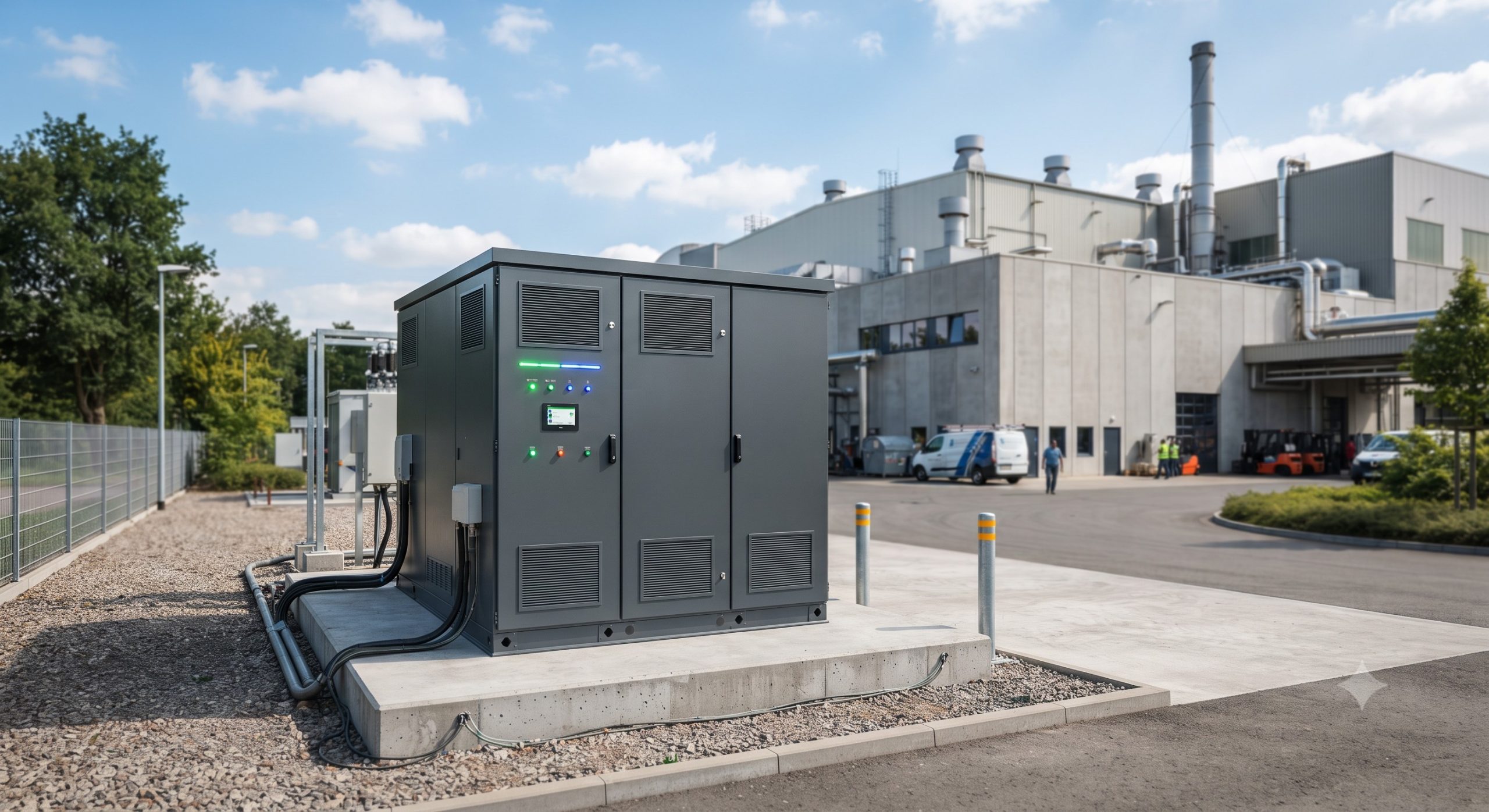
Megawatt-level energy storage is proving versatile across various high-energy-demand environments. In industrial parks, these systems are integrated with on-site solar PV to create a PV-Storage-Charging (光储充) hub, enabling EV fleets to charge with 100% renewable energy. For data centers, MW-ESS provides ultra-fast response UPS functionality while shaving the facility’s peak load to avoid massive utility demand penalties. Manufacturing plants utilize MW-scale storage to offset intermittent high-power machinery loads, stabilizing internal grid frequency and ensuring production lines remain operational during brownouts. The modular containerized design (typically 20ft or 40ft ISO containers) allows for rapid ‘plug-and-play’ installation and easy expansion from 2 MW to 20 MW by parallel connecting cabinets.

Conclusion: Future-Proofing Energy Strategy with MW-Scale Storage
Sourcing a megawatt-level energy storage system is a strategic investment that requires a deep understanding of battery chemistry, advanced thermal management, and rigorous compliance standards. By prioritizing systems with robust Liquid Cooling for superior thermal control, Tier-1 LFP cells ensuring >8000 cycles, and a certified BMS for precise cell balancing, businesses ensure high performance and asset longevity. The financial model is increasingly compelling, driven by peak-shaving, demand response, and grid participation revenue streams. As the energy transition accelerates, MW-ESS stands as the cornerstone infrastructure for C&I facilities aiming for energy autonomy, reduced costs, and zero-carbon operations.