Introduction: Why Rigorous Protocol Testing Is Non-Negotiable for BESS Safety
The global commercial energy storage market is projected to exceed $30 billion by 2030, yet the single greatest liability for C&I facility managers remains thermal runaway. In 2024 alone, over 40 grid-scale BESS incidents were reported globally, underscoring that BESS rigorous protocol testing is not merely a compliance checkbox but a critical risk-mitigation strategy. For system integrators and procurement officers, verifying performance under extreme conditions—from cell-level faults to PCS overload—demands a multi-layered approach grounded in international standards like IEC 62619 and UL 9540. This technical blog deconstructs the anatomy of a fail-safe BESS, from advanced BMS algorithms to multi-stage fire suppression, providing actionable metrics for evaluating Tier-1 LFP systems.
Core Architecture & Battery Management: The First Line of Defense in Protocol Testing
Cell-Level Safety: LFP Chemistry and SEI Integrity
At the heart of any safe BESS rigorous protocol testing regime lies the battery cell chemistry. Tier-1 LFP (Lithium Iron Phosphate) cells are the industry standard due to their olivine crystal structure, which provides exceptional thermal stability up to 500°C. However, cell safety is contingent on the Solid Electrolyte Interphase (SEI) layer’s integrity. Protocol tests often include accelerated rate calorimetry (ARC) to measure self-heating rates—with acceptable thresholds below 0.02°C/min for grade-A cells. Key metrics include Cycle Life (≥8000 cycles at 90% DoD), Round-trip efficiency (≥94%), and DOD management windows of 10%-100%.
BMS Topology: Real-Time Diagnostics and Fault Isolation
The Battery Management System (BMS) executes the first automated response during protocol testing. Advanced distributed BMS architectures, leveraging CAN bus communication, monitor voltage, current, and temperature at the cell level (sampling rates <100ms). During protocol testing, the BMS executes a series of fault injections—including cell over-voltage (triggering at 3.65V), under-voltage (<2.5V), and over-temperature (>55°C). A robust BMS must demonstrate cell balancing accuracy within ±5mV, ensuring that weak cells do not precipitate cascading failures. Furthermore, the BMS must log over 10,000 event histories to comply with IEC 62619’s functional safety requirements, enabling post-incident forensic analysis.
Thermal Management Systems: Liquid Cooling vs. Air Cooling
Thermal control is central to protocol testing for degradation prevention. Liquid cooling systems, using dielectric fluids or water-glycol mixtures, maintain cell pack temperature gradients within ≤3°C across modules—a critical parameter for ensuring cycle life longevity. In contrast, air cooling often results in gradients exceeding 8°C, accelerating anode aging by up to 20%. Rigorous protocol tests mandate thermal shock cycles (-20°C to 60°C) to validate the Liquid Cooling system’s ability to handle peak charge/discharge rates (0.5C to 1C). The testing protocol also evaluates the cooling system’s power consumption, aiming for an overall system COP (Coefficient of Performance) > 3.0.
Technical Specifications: The Parameter Registry for Compliance Audits
During a formal BESS rigorous protocol testing audit, these parameters are cross-referenced against FAT (Factory Acceptance Test) and SAT (Site Acceptance Test) criteria. Below is the mandatory checklist for any commercial ESS procurement.
| Key Parameter | Technical Specification | Protocol Test Threshold |
|---|---|---|
| Battery Chemistry | Tier-1 LFP (Lithium Iron Phosphate) | Thermal stability >500°C (ARC test) |
| System Capacity | Up to 5 MWh (modular cabinets) | +/- 2% capacity validation @ 1C |
| Cycle Life | >8000 cycles @ 90% DoD | Capacity retention ≥80% after 8000 cycles |
| Round-trip Efficiency | ≥94% (DC-DC) | Measured under 0.5C charge/discharge |
| Operating Temperature | -20°C to +55°C (ambient) | Derating curve validation |
| Cooling System | Liquid Cooling (dielectric fluid) | ΔT ≤3°C across cells @ 1C rate |
| Protection Class | IP54 (outdoor cabinet) | Dust/water ingress test |
| Compliance | IEC 62619, UL 9540, CE, UN38.3 | Full certification evidence |
| BMS Accuracy | Voltage/Current: ±1% FSR, Temp: ±1°C | Cell balancing ≤ ±5mV |
PCS Integration and Grid Synchronization Testing
The Power Conversion System (PCS) must pass grid-synchronization tests per IEEE 1547, including the ability to ride through voltage sags (0-100% nominal within 1ms). Protocol testing assesses the PCS’s bidirectional conversion efficiency under varying load conditions, with acceptable losses <2.5%. Additionally, the PCS must support both grid-tied and islanding modes, switching within <20ms to maintain supply to critical loads. LSI factors such as Demand Response readiness and EMS Dispatch latency are measured against the system’s ability to flatten load curves in C&I facilities.
Commercial ROI & Grid Support: Safety as a Profit Multiplier
While safety compliance is the primary focus, BESS rigorous protocol testing directly influences the total cost of ownership (TCO). Systems that pass comprehensive UL 9540 testing benefit from lower insurance premiums—often by 15-30% compared to uncertified systems. Moreover, proven thermal stability ensures higher availability for peak-shaving applications, where facilities can reduce demand charges by up to 40%. For industrial parks, the ability to participate in frequency regulation markets (via PCS response times <1 second) translates to additional revenue streams, accelerating ROI by 1-2 years. Data-driven analysis shows that each 1% improvement in round-trip efficiency yields a 0.5% reduction in LCOE (Levelized Cost of Energy), underscoring the economic value of a thoroughly tested BESS.
Deployment Scenarios: Real-World Protocol Validation in the Field
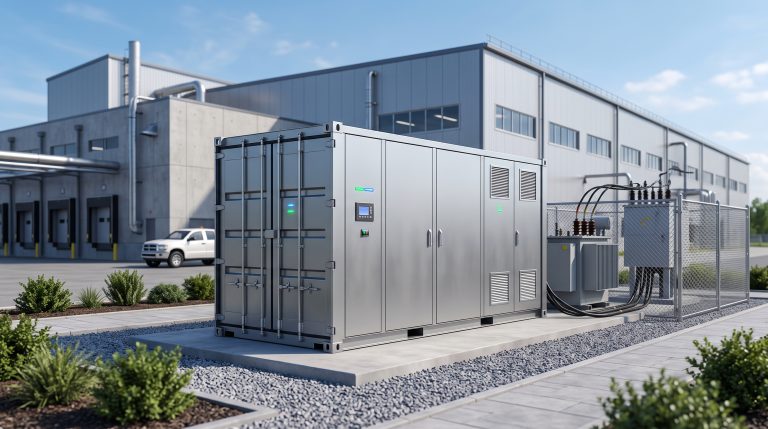
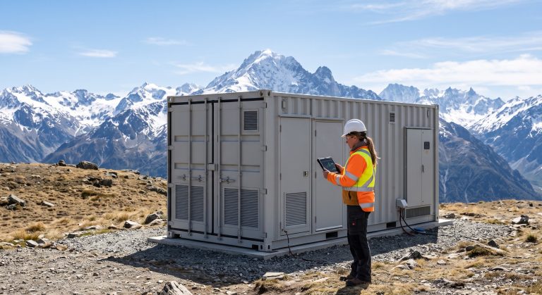
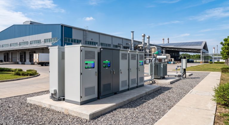
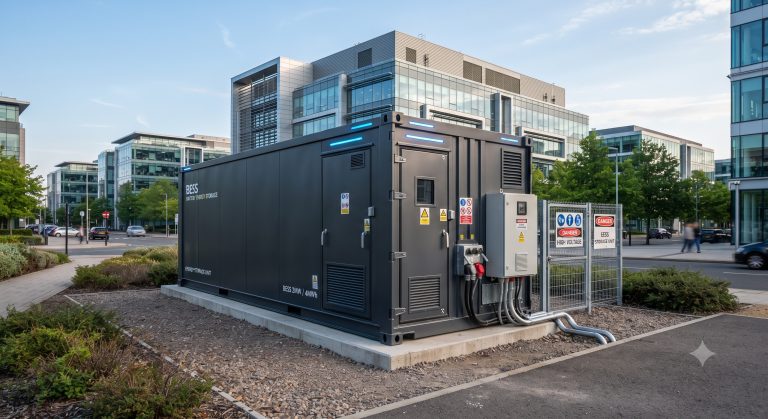
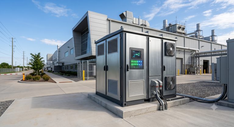
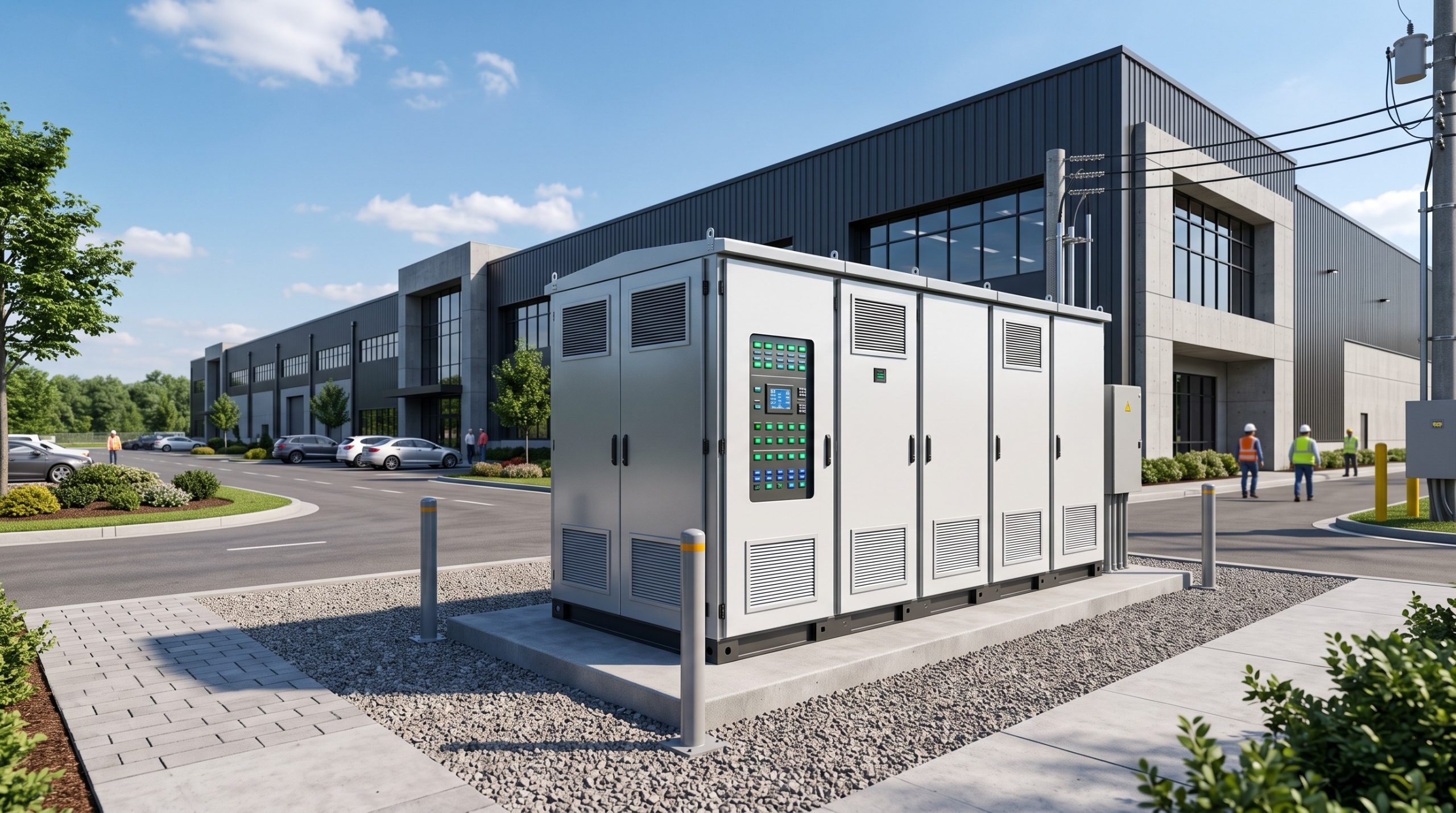
Deploying a BESS in a C&I environment, such as an EV supercharging station or a data center, introduces variables unaccounted for in controlled lab conditions. Therefore, field protocol testing includes partial discharge tests (simulating grid outages) and ambient temperature fluctuation assessments. For example, in a PV-storage-charging synergy, the BESS must withstand frequent high-C rate discharges during EV charging peaks while absorbing solar generation volatility. Real facility results indicate that systems with robust BMS and fire suppression achieve >99.9% uptime, preventing revenue loss from downtime. Furthermore, modular deployments (e.g., containerized outdoor installations) require testing of inter-cabinet busbar linkages and grounding continuity to meet CE and UN38.3 transport safety standards for lithium batteries.

Conclusion: A Call for Protocol-Driven Procurement
As the C&I sector accelerates its zero-carbon migration, the margin for error in battery safety shrinks. BESS rigorous protocol testing, anchored by advanced BMS logic, liquid cooling thermal controls, and multi-level fire suppression, is the bedrock of sustainable energy independence. For system architects and sourcing managers, the decision to prioritize deeply verified hardware over marginal cost savings is a decisive factor in long-term profitability. By adhering to the technical benchmarks and compliance frameworks outlined in this guide—from IEC 62619 to UL 9540—commercial enterprises can deploy energy storage solutions that are as financially sound as they are safe. The future of industrial energy resilience hinges on rigorous, transparent, and data-driven testing protocols that leave no room for thermal uncertainty.