Introduction
Rising industrial electricity costs, aging grid infrastructure, and increasing demand charges are squeezing commercial margins tighter than ever. From 2024 to 2026, peak demand rates in key markets like Germany, California, and Australia have surged by over 18%, forcing facility managers to seek peak shaving and energy independence solutions beyond traditional diesel generators. Enter liquid-cooled energy storage – a paradigm shift in battery energy storage systems (BESS) that delivers superior thermal control, longer cycle life, and higher round-trip efficiency than conventional air-cooled alternatives. This technical guide provides a data-driven deep dive into liquid-cooled BESS architecture, commercial ROI, and deployment strategies for C&I facilities, EV supercharging hubs, and microgrids. We cover relevant standards including IEC 62619, UL 9540, CE, and UN38.3 to help you source with confidence.
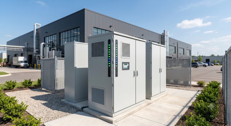
Core Architecture & Battery Management
Power Conversion System (PCS) & BMS Integration
Modern liquid-cooled BESS integrates a bi-directional PCS with efficiency typically exceeding 98.5%, coupled with a distributed Battery Management System (BMS) monitoring cell voltage, temperature, and current at sub-second intervals. The BMS ensures cell-to-cell voltage variance remains below ±20mV, preventing thermal runaway triggers common in nickel-based chemistries. EMS (Energy Management System) layer enables time-of-use arbitrage, demand response, and PV-storage-charging logic.
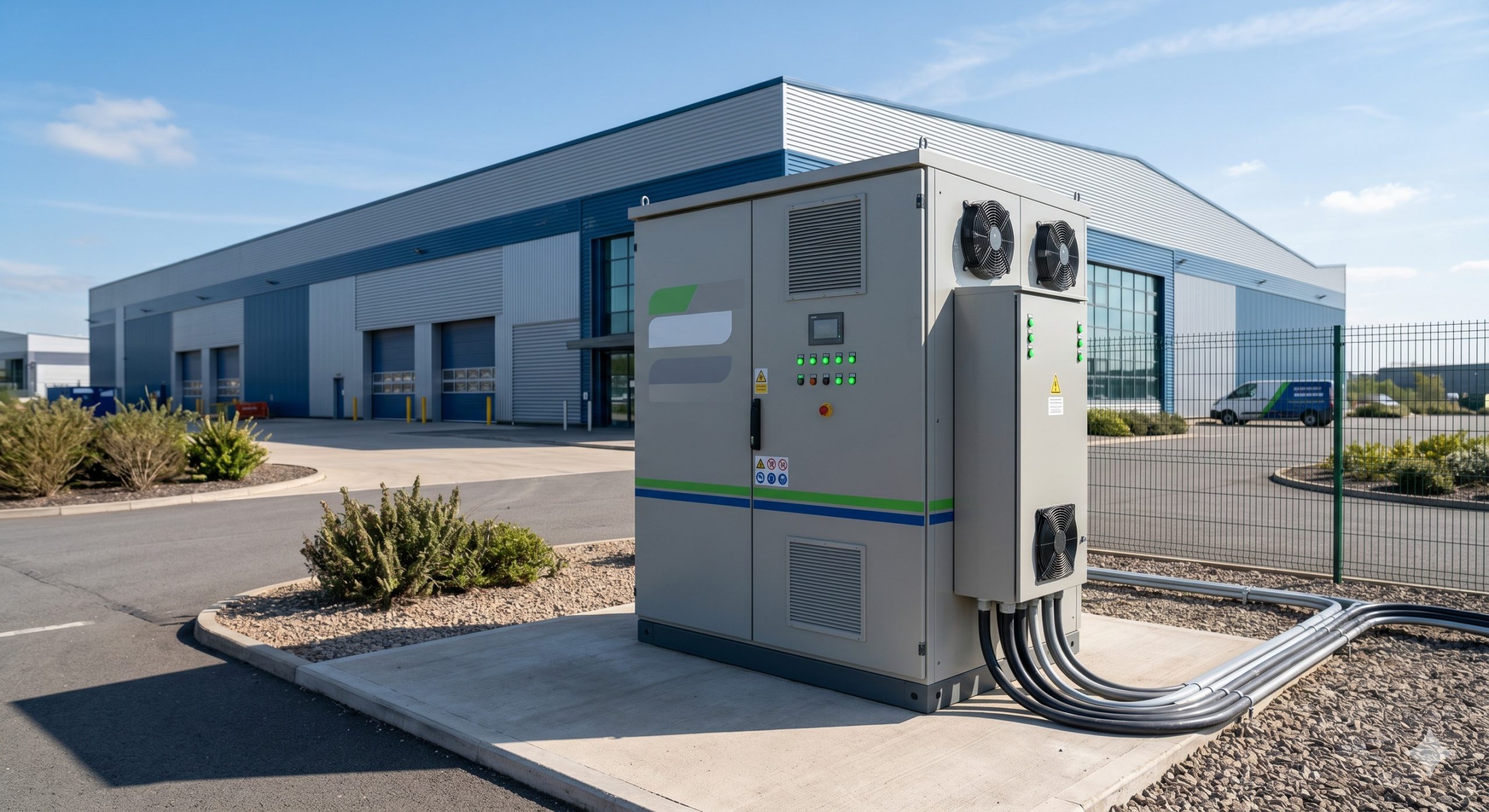
Liquid Cooling vs. Air Cooling: Thermal Control Metrics
Conventional air cooling struggles to maintain cell temperature uniformity across a 20-foot container, often yielding a 5-8°C delta between center and edge cells. This accelerates capacity fade. Liquid cooling – typically using a water-glycol mix circulating through cold plates – holds temperature uniformity within ±1.5°C across all cells. Key benefits: permits 1C to 1.5C continuous charge/discharge without derating, reduces parasitic cooling power by 30-40%, and extends cycle life to >8000 cycles at 90% DoD. Integrated fire suppression systems (aerosol or gas-based) meeting NFPA 855 are standard, with thermal runaway detection at cell level.
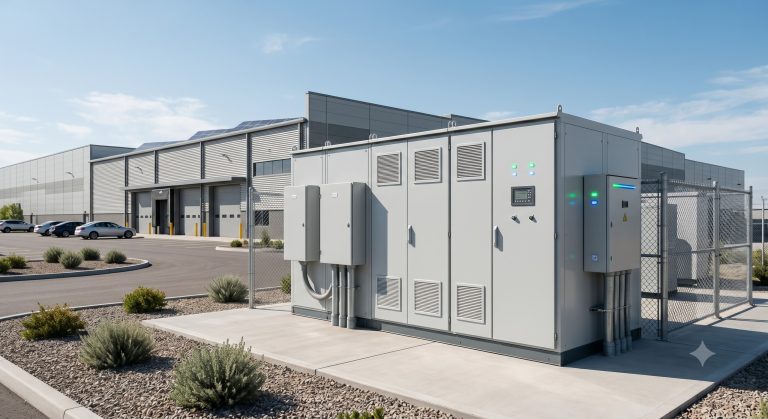
Safety & Compliance
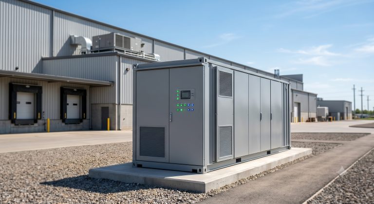
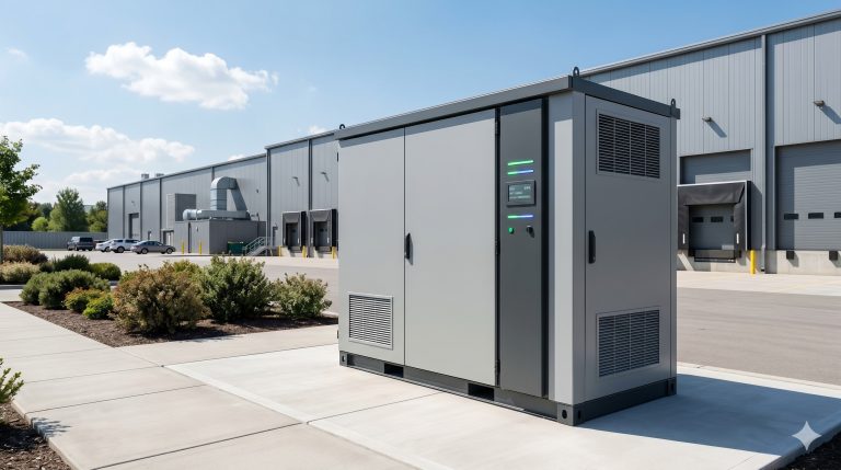
Market-ready liquid-cooled cabinets carry UL 9540A thermal runaway propagation testing, IEC 62619 for industrial batteries, CE for EU markets, and UN38.3 for transport. Many also include IP55 or IP65 ingress protection, enabling outdoor installation without additional shelters.
Technical Specifications
The table below summarizes typical parameters for a commercial-grade liquid-cooled BESS (e.g., 215kWh to 2MWh modular cabinets).
| Key Parameter | Technical Specification |
|---|---|
| Battery Chemistry | LFP (Lithium Iron Phosphate) |
| System Capacity | 215 kWh / 372 kWh / 1 MWh / 2 MWh (modular) |
| Max Charge/Discharge Rate | 1C continuous, 1.5C peak (10 sec) |
| Round-trip Efficiency (AC-AC) | ≥92% @ 1C, 25°C |
| Cycle Life | >8,000 cycles @ 90% DoD, EOL 70% SOH |
| Thermal Control | Liquid cooling (water-glycol), ΔT ≤±1.5°C across cells |
| Ingress Protection | IP55 (cabinet), IP65 (battery rack optional) |
| Safety Standards | UL 9540, IEC 62619, CE, UN38.3, NFPA 855 ready |
| Operating Temperature | -20°C to +50°C (charge), -10°C to +50°C (discharge) |
Commercial ROI & Grid Support
Liquid-cooled energy storage systems consistently outperform diesel generators and grid-only reliance on Levelized Cost of Storage (LCOS). Current LCOS for LFP-based liquid-cooled BESS ranges from $0.08–0.12/kWh, compared to $0.25–0.40/kWh for diesel peakers (including fuel and maintenance).
Peak Shaving & Demand Charge Reduction
Commercial facilities facing demand charges of $15–25/kW can achieve payback under 3 years. For a facility with a 1MW peak reduction, annual savings often exceed $40,000. Cycle life >8000 cycles ensures 15+ years of operation.
Demand Response & Grid Services
Enrolling in aggregated demand response programs provides additional revenue of $50–150/kW-year. Advanced EMS supports fast frequency response (response time <50ms) compliant with IEEE 1547.
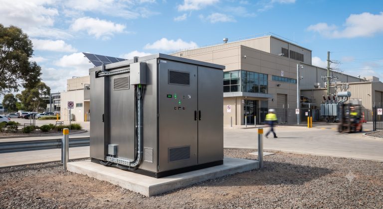
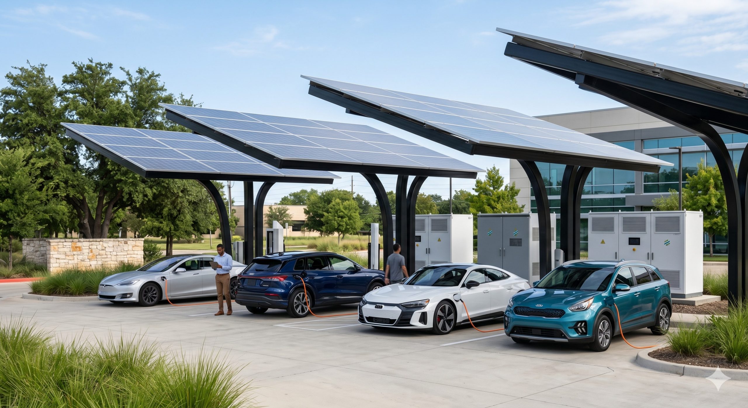
PV-Storage-Charging Integration
Liquid cooling’s high thermal inertia perfectly suits the variable loads of EV fast-charging. A 500kW PV array paired with 1MWh liquid-cooled BESS can power 4 ultra-fast chargers (150kW each) while reducing grid connection costs by up to 60%.
Deployment Scenarios
Three high-ROI deployment models dominate the C&I landscape:
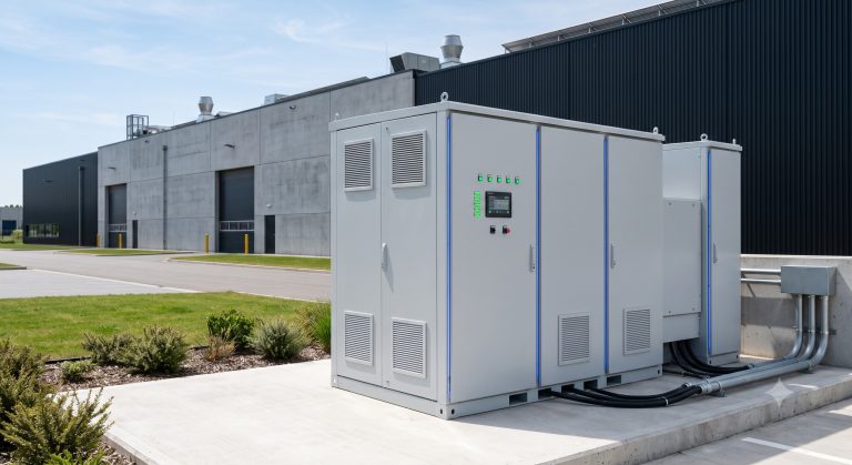
- Manufacturing & Industrial Parks: Steel mills, chemical plants, and automotive factories use 2-10MWh systems to shave peak loads and ensure production continuity during grid faults.
- EV Supercharging Hubs: Liquid-cooled BESS buffers grid-constrained sites, enabling 350kW charging without costly transformer upgrades. Battery capacity typically 1-4MWh per 8-12 chargers.
- Islanded Microgrids & Remote Mines: Replacing diesel generators with solar + liquid-cooled BESS achieves 70-90% diesel savings. Cycle depths often 80% daily, requiring thermal stability assured by liquid cooling.
Conclusion
The transition to liquid-cooled energy storage represents not an incremental improvement but a fundamental engineering leap for C&I energy management. Superior thermal uniformity directly translates to lower LCOS, higher safety margins, and compatibility with high-load applications like EV fleets. As grid instability increases and carbon policies tighten (EU CBAM, US IRA incentives), deploying UL9540/IEC62619-certified liquid-cooled BESS is a proven hedge against energy inflation. For procurement managers and project developers, prioritizing liquid cooling over legacy air-cooled designs will define asset profitability through 2035 and beyond.