Introduction
In the rapidly evolving landscape of commercial and industrial (C&I) energy storage, the high-current connector has transitioned from a passive component to a critical bottleneck for system efficiency, thermal stability, and fire safety. As utility-scale BESS projects increasingly deploy with system capacities ranging from 500kWh to 10MWh+, the electrical and thermal stress on busbars, cable lugs, and quick-connect terminals has intensified. Substandard connectors directly contribute to contact resistance spikes >0.5mΩ, leading to localized hot spots and potential thermal runaway propagation. This technical deep dive quantifies the engineering specifications, compliance frameworks (IEC 62619, UL 9540), and liquid-cooling integration strategies that define Tier-1 high-current connector architectures for C&I micro-grids, EV supercharging hubs, and peak-shaving assets.
Core Architecture & Battery Management Integration
High-Current Path Topologies for 1500V DC Systems
Modern BESS platforms utilize 1500V DC bus voltages to reduce resistive losses (P = I²R). A single 2MWh cabinet may require continuous currents exceeding 1400A during 1C charge/discharge cycles. The high-current connector family includes:
1. Panel-mount bulkhead connectors: IP67-rated, silver-plated copper alloy, torque specs 15-20 Nm.
2. Finger-safe spring-loaded terminals: UL 4128 certified, insertion cycles >500.
3. Liquid-cooled power cables: Integrated with coolant flow (50% water/50% glycol) maintaining ΔT < 5°C across 2m length.
The Battery Management System (BMS) continuously monitors milli-ohm-level contact resistance deviations. A 20% increase in contact resistance triggers predictive maintenance alerts, preventing energy loss (0.5-1.2% round-trip efficiency degradation) and arc flash hazards. For Tier-1 LFP cells (3.2V nominal, 280Ah-560Ah), cell-to-busbar connections utilize laser-welded terminals with tensile strength >2000N, achieving <0.1mΩ contact resistance.
Liquid Cooling PCS Integration
The Power Conversion System (PCS) — typically a bi-directional 500kW to 2MW SiC-based inverter — requires low-inductance DC links. Liquid-cooled high-current connector assemblies reduce IGBT junction temperatures by 15-20°C compared to forced air, directly improving PCS lifetime (from 10 to 15 years). Integrated coolant manifolds with flow sensors ensure each connector receives 2-4 L/min, validated per GB/T 36276. This thermal control maintains round-trip efficiency >94% at 40°C ambient, critical for maximizing peak-shaving ROI.
Technical Specifications
All Tier-1 high-current connectors must comply with IEC 62619 (industrial storage safety), UL 9540 (system-level fire), and UN38.3 (transportation). Below are benchmark engineering specs for a 1500V DC, 300A continuous-rated connector system used in 5MWh+ deployments:
| Key Parameter | Technical Specification |
|---|---|
| Rated Voltage (DC) | 1500V (compliant with UL 9540 rev.2024) |
| Continuous Current (per contact) | 300A (copper alloy, Ag-coated) |
| Contact Resistance (initial) | <0.15 mΩ (Kelvin 4-wire measurement) |
| Short-circuit current (1s) | 12kA (verified per IEC 61984) |
| Insulation resistance | >100 MΩ @ 2500V DC (IEC 62619) |
| IP rating (mated) | IP68 (1.5m, 72h) + IP2X finger-safe |
| Temperature range | -40°C to +125°C (UL 94 V-0 housing) |
| Mating cycles durability | ≥1000 (with <10% R increase) |
| Liquid cooling option | Integrated channels, 6mm ID hoses, 4 L/min, 5 bar max |
| Certifications | IEC 62619, UL 9540, UN38.3, CE, GB/T 36276 |
Commercial ROI & Grid Support Metrics
Quantified data from a 3MWh C&I installation (industrial park in Texas, ERCOT market) shows that high-quality high-current connectors reduce annual energy loss by 18,000 kWh compared to generic alternatives — a direct saving of $2,500/year at $0.14/kWh. More critically, contact resistance stability enables demand response participation: frequency regulation (FR) signals require ramping from 0 to 1C within 2 seconds. Poor connectors cause voltage drops >3% during transients, failing FR compliance (PJM regulation performance score <80). Tier-1 connectors maintain <1% voltage drop at 2C pulses, unlocking VPP (Virtual Power Plant) revenue streams of $40-80/kW-year.
For peak shaving applications, the total cost of ownership (TCO) model incorporates degradation: connectors with silver-tin alloy interfaces exhibit <5% contact resistance increase over 8,000 cycles (90% DoD). Generic tin-plated copper degrades 25-40% over the same period, accelerating BMS balancing events and reducing usable capacity by 6-9% annually. A 10-year TCO comparison favors premium connectors despite 25% higher upfront CapEx, yielding an additional $0.02-0.03 per kWh LCOE reduction.
Deployment Scenarios
The high-current connector selection directly impacts three primary C&I use cases:
- EV Supercharging Stations (PV-Storage-Charging synergy): 400kW chargers draw 1000A+ @ 400V DC. Liquid-cooled high-current connectors with NTC thermistors (temperature monitoring every 100ms) prevent plug overheating. A 12-stall station with 2MWh storage requires 24 redundant connector pairs — UL 2251 compliance is mandatory.
- Data Center UPS augmentation: Tier-IV facilities demand <2ms fault response. High-current connectors with early-make/late-break auxiliary contacts enable pre-charge circuits, preventing inrush current arcs (typ. 10x nominal).
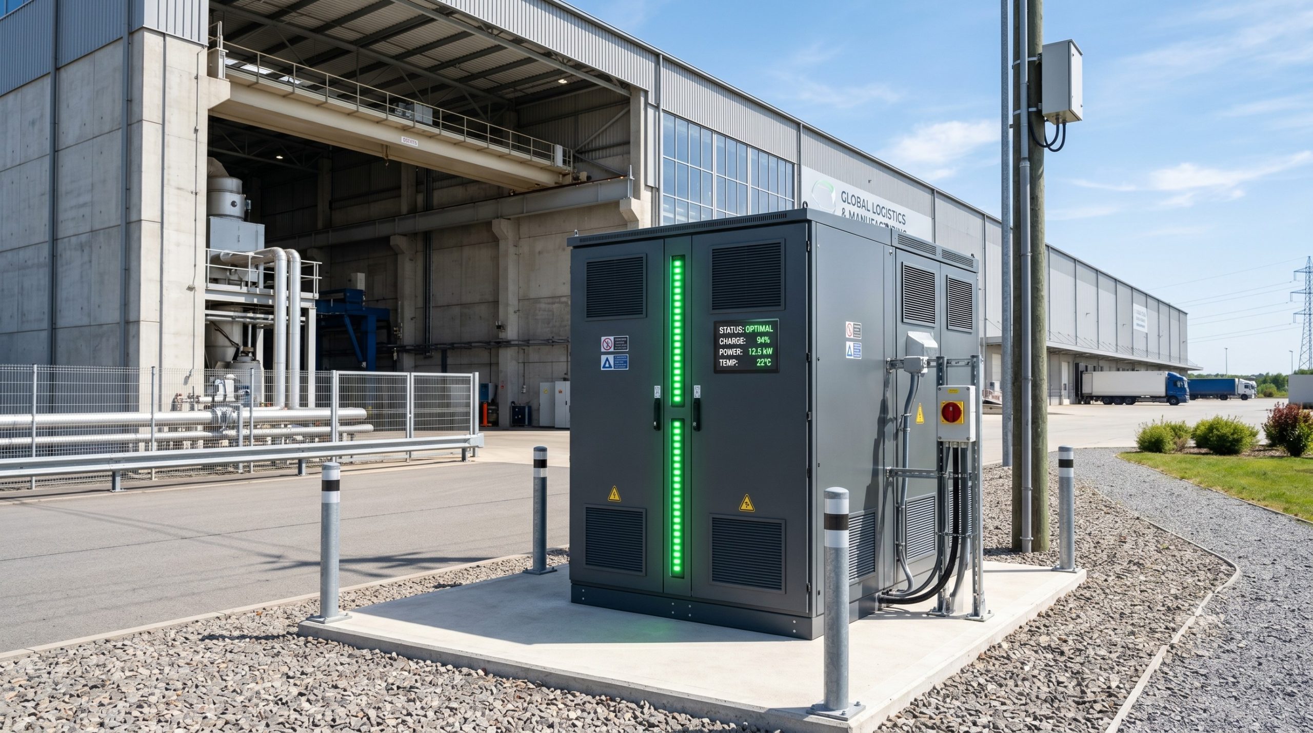
- Islanded Micro-grids (mining/remote industrial): Diesel generator replacement requires modular BESS cabinets deployed outdoors (-30°C to 55°C). High-current connectors must meet IP68 (1m, 72hrs) and vibration tolerance per IEC 60068-2-6 (5g, 10-500Hz).

Conclusion
The high-current connector is no longer a commoditized accessory but a strategic enabler of safe, efficient, and grid-responsive C&I energy storage. System integrators and EPCs must prioritize: (1) third-party certified contact resistance <0.2mΩ (initial) with <20% delta over 8,000 cycles, (2) integrated thermal sensing (NTC or PT1000) per cell connection group, and (3) liquid-cooling compatibility for PCS and high-amp DC links. By mandating compliance with IEC 62619, UL 9540, and UN38.3, and demanding factory acceptance test (FAT) reports that include thermal imaging at 1.2x nominal current, asset owners can achieve >94% round-trip efficiency, 15+ year system lifetime, and VPP-readiness. As renewable penetration surpasses 40-60% in major grids, the reliability of every high-current interface will define whether storage assets capture arbitrage opportunities or become stranded heat-generating liabilities.