COMMERCIAL SYSTEMS ENGINEERING REFERENCE MANUAL: C&I BATTERY CABINET WEIGHT AND FOOTPRINT SHEET
OFFICIAL PRODUCT OVERVIEW & DATASHEET
This document serves as the definitive engineering reference for the physical attributes and system specifications of our latest generation of Commercial and Industrial (C&I) Battery Energy Storage Systems (BESS). It is intended for project developers, civil engineers, and facility planners requiring precise mechanical and electrical data for system integration, site preparation, and logistics planning.
PRODUCT IDENTIFICATION & SCOPE
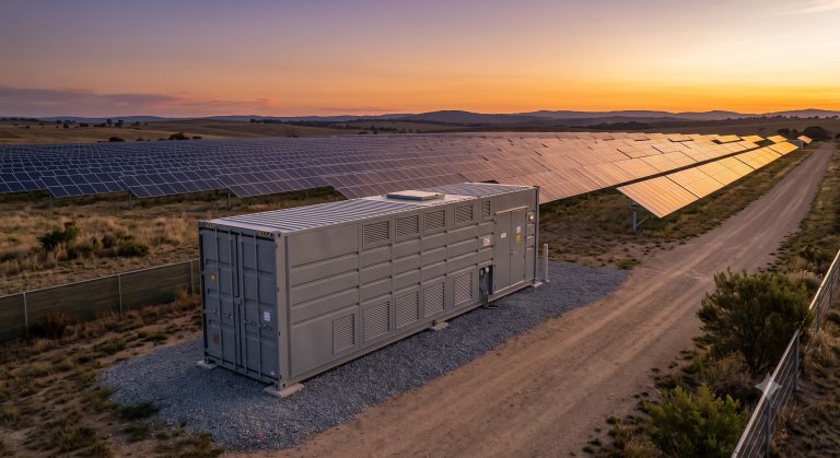
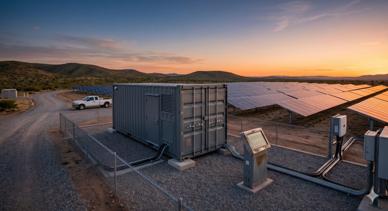
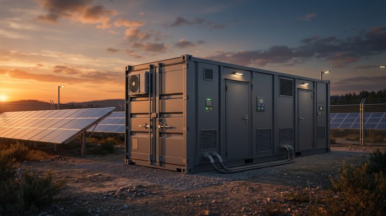
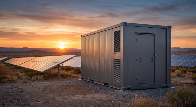
The C&I cabinet platform is designed as a modular, outdoor-rated, and turnkey energy storage solution. This document focuses specifically on the “Weight and Footprint Sheet,” detailing the physical dimensions, base weight, deployment clearances, and ground load-bearing requirements essential for a successful installation. The platform leverages a high-density, Tier-1 LFP (Lithium Iron Phosphate) cell architecture, managed by a proprietary 3-tier Battery Management System (BMS) and integrated with a bi-directional Power Conversion System (PCS).
INTERNAL BESS TOPOLOGY & MECHANICAL ARCHITECTURE
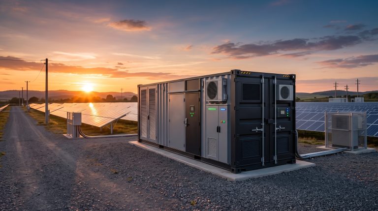
The system is housed within an IP54-rated, heavy-gauge steel chassis, engineered for both indoor and outdoor deployment. The internal topology is segmented into three primary zones:
1. BATTERY ZONE: This section houses the modular battery racks, comprising LFP prismatic cells configured in series to achieve nominal system voltages. The rack structure is designed to segregate cells for optimal thermal management and to prevent thermal propagation.
2. POWER CONVERSION ZONE: This isolated compartment contains the PCS, which efficiently converts DC power to AC and vice versa. The zone includes integrated EMI filters and grid-tie contactors.
3. CONTROL & SAFETY ZONE: This is the central hub for the BMS, Energy Management System (EMS) controller, fire suppression control panel, and communications gateways.
MECHANICAL PARAMETERS & FOOTPRINT
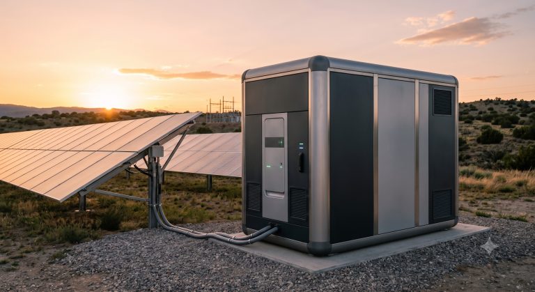
The cabinet’s footprint is optimized for standard shipping pallets and shipping container utilization, minimizing logistical costs while maximizing energy density.
– CABINET DIMENSIONS (W x D x H): 1,200 mm x 1,400 mm x 2,200 mm (Standard configuration). Variations exist for extended runtime or high-voltage models.
– TOTAL DRY WEIGHT: Approx. 2,500 kg (Base model). This weight includes all structural components but excludes internal coolant and optional external fire suppression agent reserve.
– OPERATING WEIGHT: Approx. 2,650 kg (with internal coolant and standard operating fluids).
– MAXIMUM GROUND BEARING PRESSURE: 18.5 kN/m². This parameter is critical for slab or platform design.
– FOOTPRINT AREA: 1.68 m² (11 ft²). The cabinet features a standardized base frame with integrated fork-lift pockets and lifting lugs for safe handling.
THERMAL PROTECTION & LIQUID COOLING MECHANISMS
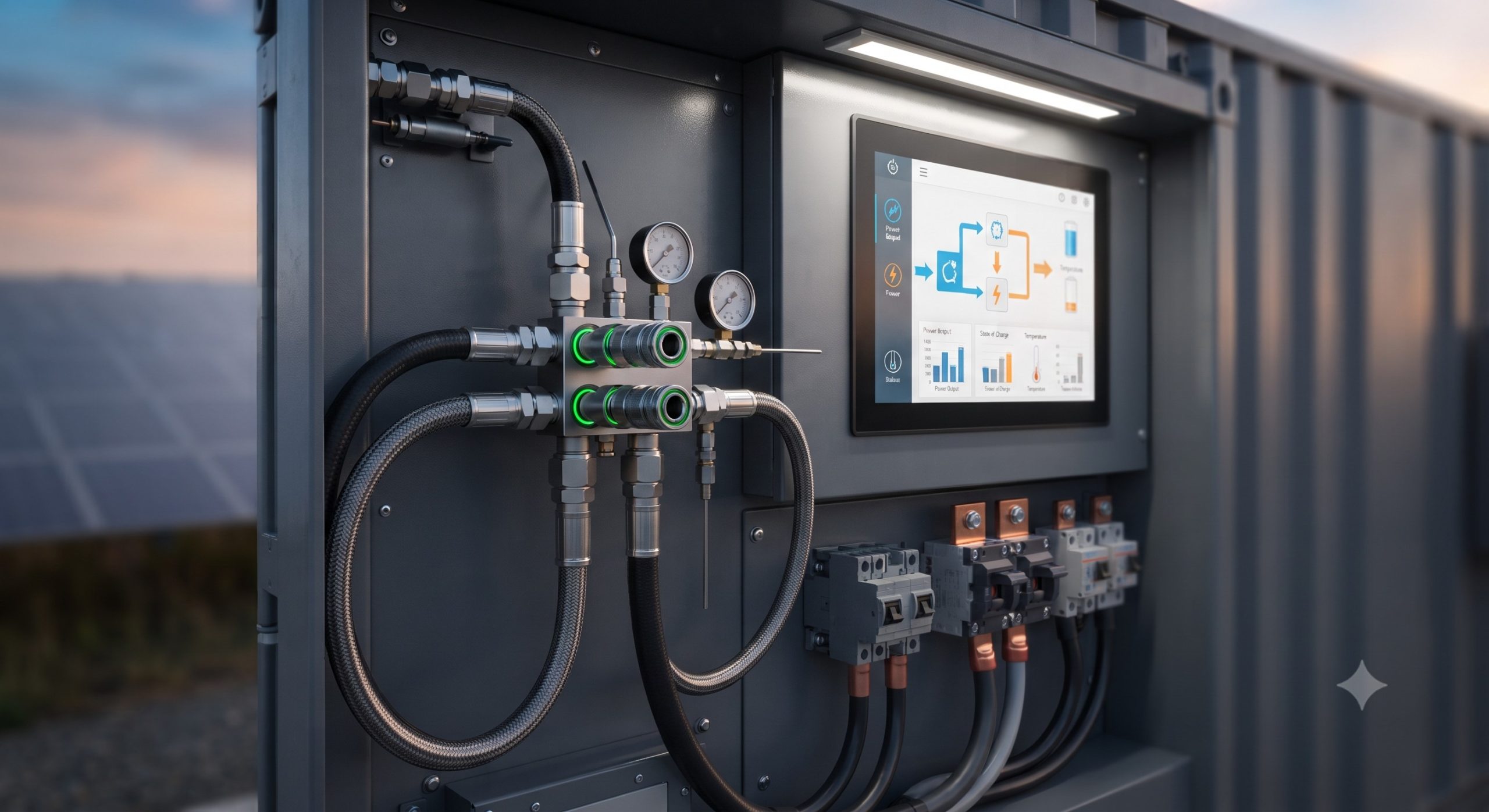
Thermal stability is paramount to ensuring cycle life and safety. Our system employs a sophisticated, closed-loop liquid cooling architecture.
– COOLING METHOD: Smart variable-speed liquid cooling with a dedicated chiller unit. The coolant is a dielectric, water-glycol mixture circulated through aluminum cold plates directly bonded to each battery module.
– OPERATING TEMPERATURE RANGE: Ambient operation is supported from -20°C to +50°C. The cooling system can reject 100% of the heat generated during full-power charging and discharging cycles.
– TEMPERATURE CONTROL PRECISION: +/- 1.5°C across all cell surfaces. This precision ensures cell-to-cell temperature consistency, preventing capacity stratification and extending the operational lifespan.
OPERATIONAL ADVANTAGES & KEY CAPABILITIES
The engineering excellence of this cabinet translates directly into superior operational performance for C&I applications, including peak shaving, load shifting, and grid stabilization.
KEY FEATURES
– Feature 1: Tier-1 LFP Cell Integration: The system utilizes prismatic LFP cells from certified Tier-1 suppliers, renowned for their intrinsic thermal safety, long cycle life (6,000+ cycles at 25°C), and flat voltage discharge curve.
– Feature 2: Closed-Loop Liquid Cooling: The integrated liquid cooling system maintains optimal operating temperatures even in extreme ambient conditions, significantly improving system round-trip efficiency (RTE > 92%) and capacity retention.
– Feature 3: Modular High-Voltage DC Busbar: The internal DC busbar architecture allows for flexible energy capacity configurations by simply adding or removing battery modules, facilitating on-site scalability from 100kW to 1MW+.
– Feature 4: 3-Tier BMS Active Equalization: The embedded BMS employs active cell balancing to maximize usable capacity, ensures State-of-Charge (SOC) and State-of-Health (SOH) accuracy, and provides multi-layer protective shutdown.
– Feature 5: IP54 & C5 Corrosion Protection: Robust ingress protection and corrosion-resistant coatings (C5 classification) guarantee long-term reliability in coastal, industrial, and high-humidity environments.
| Parameter | Specification |
|---|---|
| Nominal Capacity (Base) | 215 kWh |
| Nominal Capacity (Extended) | 372 kWh (Parallel configuration) |
| Cooling Method | Smart Liquid Cooling (Closed-Loop, Dielectric Coolant) |
| Cell Chemistry | Tier-1 LFP (Lithium Iron Phosphate) |
| Dimensions (W x D x H) | 1,200 mm x 1,400 mm x 2,200 mm |
| Total Dry Weight | ~2,500 kg |
| Operating Weight | ~2,650 kg |
| Maximum Bearing Pressure | 18.5 kN/m² |
| Protection Class | IP54 / C5 Corrosion Protection |
| Communication Protocols | Modbus TCP, CAN, IEC 61850 |
SPECIFICATION MATRIX & PARAMETER REGISTRY
The following table details the core physical and electrical parameters relevant to engineering and procurement evaluation.
| Parameter | Specification |
|---|---|
| Nominal Capacity (Base) | 215 kWh |
| Nominal Capacity (Extended) | 372 kWh (Parallel configuration) |
| Cooling Method | Smart Liquid Cooling (Closed-Loop, Dielectric Coolant) |
| Cell Chemistry | Tier-1 LFP (Lithium Iron Phosphate) |
| Dimensions (W x D x H) | 1,200 mm x 1,400 mm x 2,200 mm |
| Total Dry Weight | ~2,500 kg |
| Operating Weight | ~2,650 kg |
| Maximum Bearing Pressure | 18.5 kN/m² |
| Protection Class | IP54 / C5 Corrosion Protection |
| Communication Protocols | Modbus TCP, CAN, IEC 61850 |
REGULATORY COMPLIANCE & STANDARDS CERTIFICATION
Full compliance with international standards ensures the asset is insurable, grid-compliant, and safe for operation in global markets.
– Safety Compliance: UL 9540, UL 1973, IEC 62619, and IEC 62477. The system has been rigorously tested for thermal runaway propagation and is equipped with an aerosol fire suppression system (per NFPA 855).
– Grid Compliance: IEEE 1547 and IEC 61727 are met for grid interconnection, ensuring seamless integration and anti-islanding protection.
– Transportation Compliance: UN 38.3 certified for safe transport of lithium batteries.
– Environmental Compliance: RoHS and REACH compliant, ensuring no hazardous materials are used in the construction process.
FACILITY LAYOUT & DEPLOYMENT RECOMMENDATIONS
For optimal performance and safety, we recommend the following for facility layout and installation.
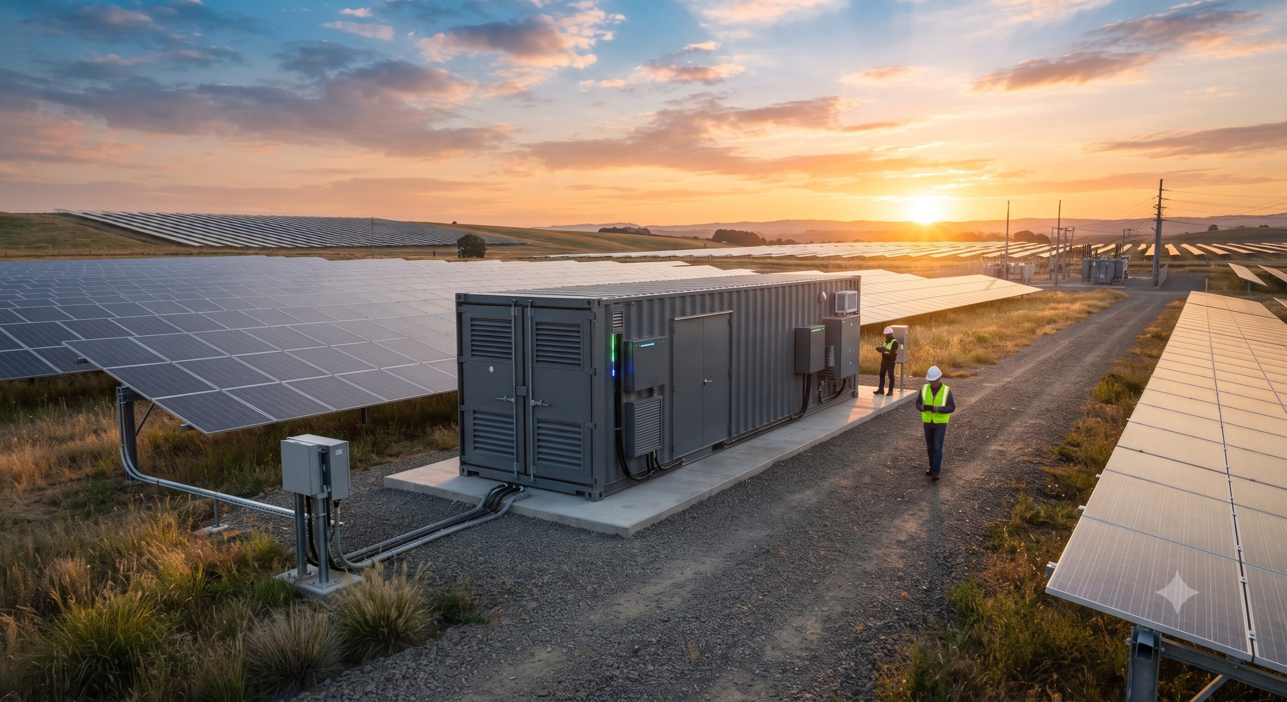
– MINIMUM CLEARANCE: Front access: 1,200 mm; Rear access: 800 mm; Side clearance: 500 mm.
– FOUNDATION: A flat, level concrete pad (minimum 300mm thick) with a compressive strength of 25 MPa or greater is required.
– CABLE ENTRY: Bottom-entry cable glands are standard for AC/DC power, communications, and grounding. The cable conduit trenches must be planned to align with the cabinet base.
– VENTILATION: Ambient ventilation must be provided to ensure ambient air temperatures do not exceed +50°C. The liquid cooling system rejects heat to the ambient environment via an external air-to-liquid heat exchanger.
INDUSTRY OUTLOOK & CONCLUSION
Our C&I Battery Cabinet represents a paradigm shift in distributed energy storage. The precise engineering documented in this “Weight and Footprint Sheet” enables project planners to confidently embed this asset into their energy infrastructure. The combination of a minimal footprint, high energy density, and advanced liquid cooling ensures that this system offers one of the lowest total cost of ownership (TCO) in the market. It stands as a robust, reliable, and safe foundation for modern C&I energy management and sustainability strategies.
📥 Download Technical Specification
Click the button below to view or download the full official PDF datasheet.