CABLE GLAND – COMMERCIAL SYSTEMS ENGINEERING REFERENCE MANUAL
PRODUCT IDENTIFICATION
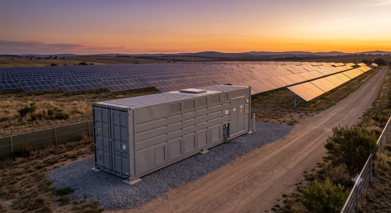
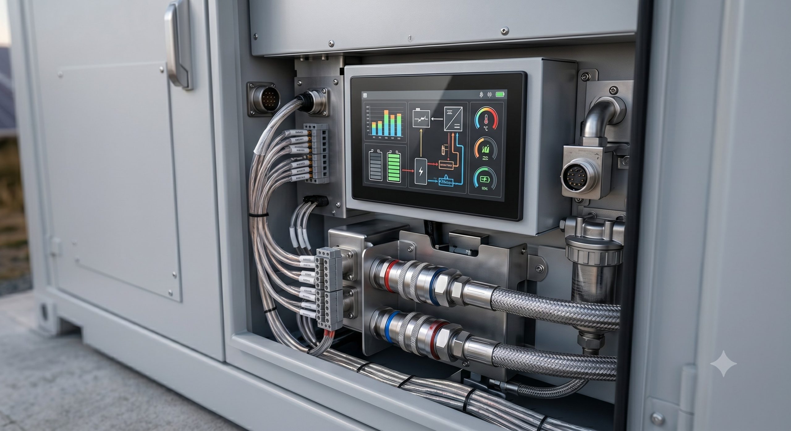
The Cable Gland assembly represents a critical interface component within the broader Battery Energy Storage System (BESS) architecture. Engineered for utility-scale and commercial & industrial (C&I) storage platforms, this ingress protection (IP) and cable management solution ensures the secure, environmentally sealed, and electrically continuous passage of power and control cables into the main enclosure. Designed with a modular, multi-entry layout, the unit supports high-current DC and AC power feeds, communication lines, and auxiliary power circuits, acting as the primary physical and electrical barrier between the internal high-voltage DC busbar and external grid or generation assets. Its robust construction aligns with the high-reliability demands of Tier-1 energy storage vendors, supporting typical capacities ranging from 200 kWh to over 5 MWh per containerized block. The assembly offers an integrated approach to cable routing, combining strain relief, EMC grounding, and environmental sealing in a single, compact footprint.
INTERNAL BESS TOPOLOGY
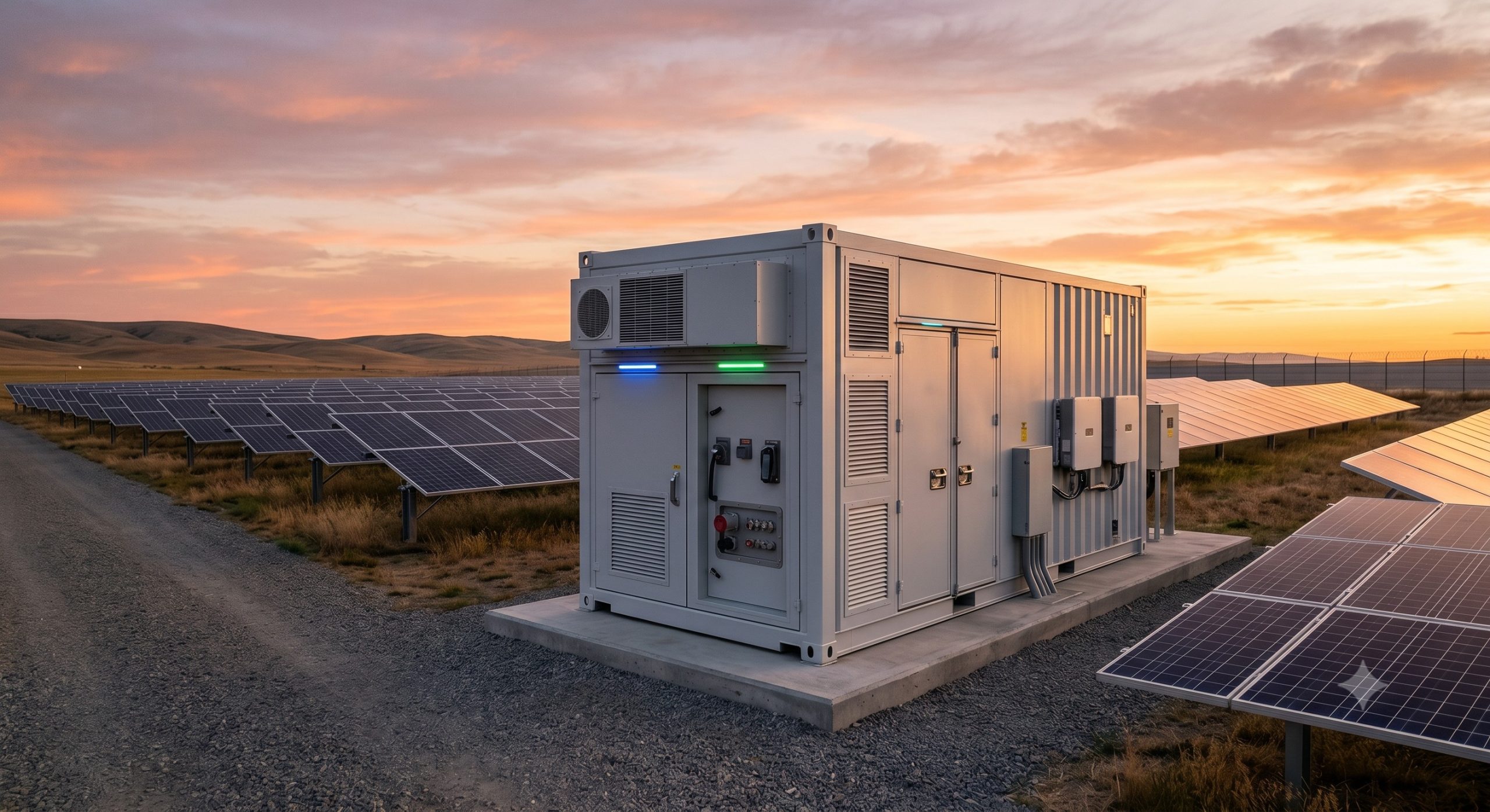
Within the overarching BESS topology, the Cable Gland is positioned at the interface point between the external power infrastructure (PV arrays, grid connection, or PCS AC side) and the internal DC busbar or inverter input stage. It facilitates the physical entry of multi-core cables, managing the transition from outdoor-rated cabling to internal busbar systems or terminal blocks. The gland system is integrated with the main enclosure’s fire-resistant and thermal insulation layers to maintain the structural integrity of the fire-rated compartment. It is designed to accommodate a wide range of cable cross-sections (typically 4 AWG to 500 MCM), ensuring compatibility with parallel inverter configurations and the high-current feeds associated with MWh-scale systems. The core topology incorporates an internal grounding bar, specifically designed to bond cable armoring and shields directly to the main earth point, a critical feature for maintaining a low-impedance path for fault currents and electrostatic discharge. The mounting plate is engineered with a grid of pre-drilled knockouts, allowing flexible, site-specific configuration to match varying cable entry requirements, thus preserving the enclosure’s IP rating across all possible deployment scenarios.
THERMAL PROTECTION MECHANISMS
The Cable Gland’s thermal management is a fundamental aspect of its design, ensuring operational integrity even under extreme fault or ambient conditions. The body is constructed from nickel-plated brass or aluminum alloy, selected for its high thermal conductivity to dissipate heat generated by high-current cable connections. A non-combustible, halogen-free insulating insert is utilized to create a barrier against arc flash propagation from the internal busbar to the external environment. In the event of a thermal runaway event, the gland’s multi-compression seal is engineered to maintain its integrity for a minimum duration as required by UL 9540, preventing the egress of flammable gases or propagation of flames through the cable entry points. The assembly’s dynamic temperature range is validated from -40°C to +105°C, ensuring reliable service across diverse global climates and maintaining its IP65/IP66 ingress protection rating under extreme thermal cycling. The sealing elements incorporate a pressure-relief feature that subtly adjusts to internal air pressure variations without compromising the seal, preventing moisture ingress due to the ‘breathing’ effect that occurs during daily temperature fluctuations.
OPERATIONAL ADVANTAGES
The Cable Gland offers tangible operational advantages that streamline deployment and enhance long-term system reliability. Its ‘click-and-torque’ design reduces installation time by allowing for rapid cable preparation and termination, minimizing the labor costs associated with site commissioning. The integrated, multi-layer sealing system provides redundant protection against water and dust ingress, significantly reducing the risk of electrical failures and extending the service life of internal components. This design eliminates the need for separate cable potting or specialized sealing tapes, ensuring a clean, professional installation. The unit supports a wide cable diameter range within each entry point, offering flexibility to future-proof the system against capacity upgrades or changes in interconnection requirements. Furthermore, the integrated EMC shielding feature ensures that the gland provides a 360-degree contact with the cable’s screen, effectively mitigating electromagnetic interference (EMI) that can disrupt sensitive BMS and EMS communications. The standardized mounting pattern is compatible with all major enclosure manufacturers, simplifying logistics and aftermarket support.
SPECIFICATION MATRIX
| Parameter | Specification |
|---|---|
| Nominal Cable Range | 14 AWG – 500 MCM (flexible/stranded copper) |
| Ingress Protection Rating | IP66 / IP67 (IEC 60529) |
| Operating Temperature Range | -40°C to +105°C |
| Material Body | Nickel-Plated Brass / Aluminum Alloy |
| Flammability Rating | UL 94 V-0 (Halogen-Free Insulating Insert) |
| Mechanical Impact Rating | IK10 (IEC 62262) |
| Corrosion Resistance | ≥ 720 hours salt spray (ASTM B117) |
| EMC Protection | 360° cable screen contact for EMI mitigation |
| Safety Compliance | UL 9540, IEC 62619, IEC 62477 |
REGULATORY COMPLIANCE
The Cable Gland is designed and tested to comply with a comprehensive suite of international standards and certifications relevant to energy storage and electrical infrastructure. It holds IP66/IP67 ratings per IEC 60529, confirming its protection against powerful water jets and temporary submersion. The construction materials and design are certified to meet the flame-retardant and halogen-free requirements of UL 94 V-0. The assembly is fully compliant with the fire and safety requirements of UL 9540 for stationary energy storage systems, specifically concerning flame propagation and ingress protection. It is tested to the rigorous mechanical impact and corrosion resistance standards of IEC 62262 and ASTM B117. EMC performance is validated per IEC 61000-6-2 and IEC 61000-6-4, covering immunity and emissions for industrial environments. This ensures the Cable Gland contributes directly to the system’s overall certification for grid interconnection, requiring no additional specialized testing.
📥 Download Technical Specification
Click the button below to view or download the full official PDF datasheet.