BATTERY CLUSTER PARALLEL WIRING INSTRUCTIONS
OFFICIAL COMMERCIAL BESS TECHNICAL OVERVIEW & DATASHEET
EXECUTIVE SUMMARY
This document provides comprehensive technical guidance for the parallel wiring of battery clusters within commercial Battery Energy Storage Systems (BESS). Proper parallel interconnection of battery clusters is critical for achieving system-level capacity scaling, ensuring balanced current distribution, and maintaining long-term operational reliability. This datasheet defines the engineering principles, safety protocols, and hardware specifications for deploying multi-cluster BESS configurations. The guidelines detailed herein are applicable to containerized and cabinet-type storage solutions based on Tier-1 LFP cell technology. Adherence to these wiring instructions ensures optimal round-trip efficiency, mitigates circulating current risks, and extends the service life of the entire storage asset.
SYSTEM ARCHITECTURE & SAFETY
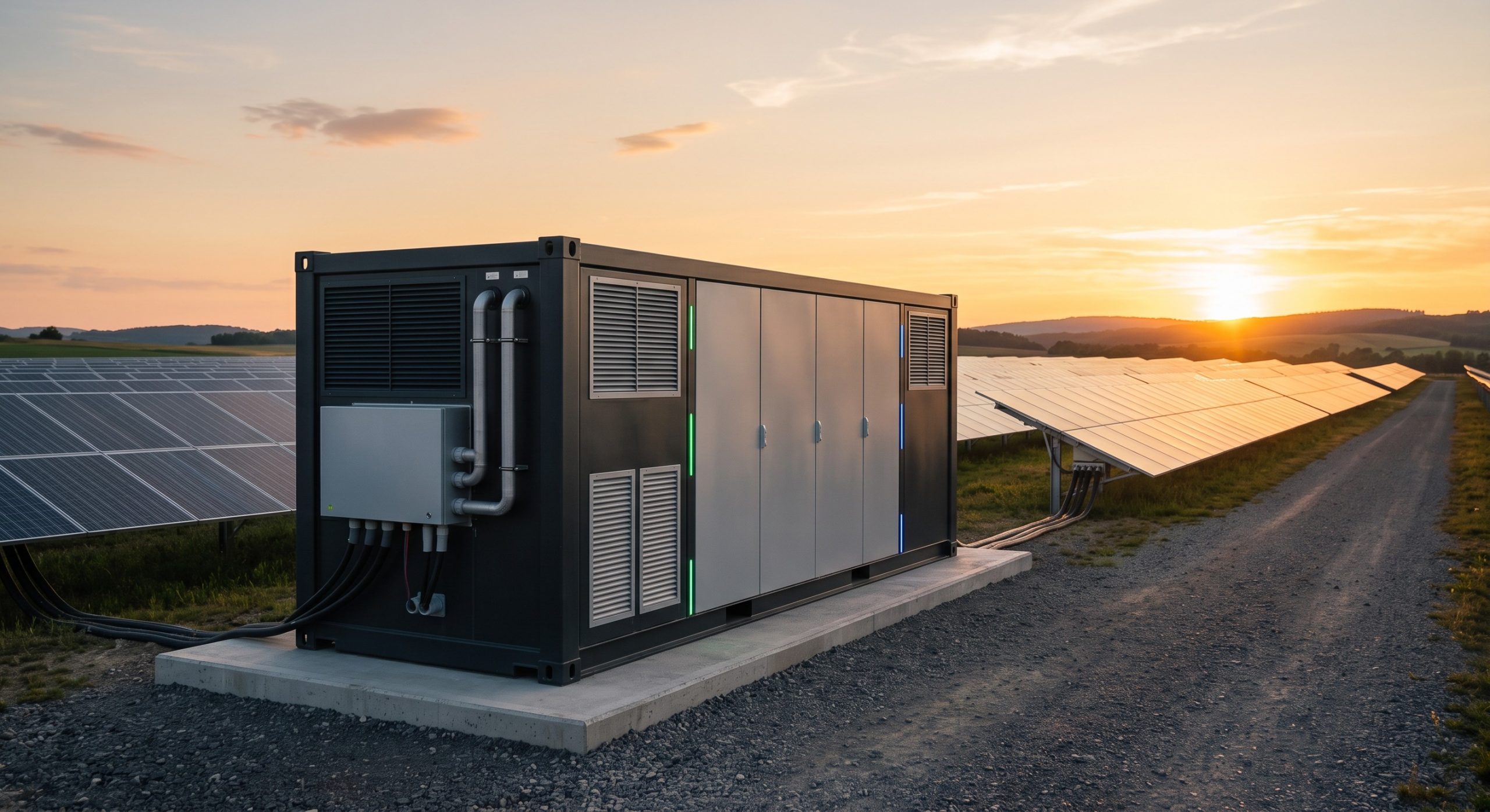
The baseline BESS architecture is designed around a modular cluster topology. Each battery cluster comprises multiple rack-mounted battery modules managed by a dedicated high-voltage Battery Management System (BMS) slave controller. The parallel wiring strategy involves interconnecting these clusters at a common DC busbar within the power conversion system (PCS) cabinet. This distributed topology enables flexible capacity expansion while maintaining independent cluster-level protection and control.
SAFETY PROTOCOLS FOR PARALLEL WIRING
– Pre-Charge Sequence: Prior to parallel closure, a pre-charge resistor network must be engaged to limit inrush current to less than 10% of nominal cluster current. This mitigates DC bus capacitor charging surges that could damage contactors or power semiconductors.
– Contactor Interlocking: Each cluster output is equipped with a DC contactor and fuse. The BMS enforces a strict interlocking logic that prevents parallel connection unless voltage differentials between clusters are less than ±5V. A voltage matching algorithm is activated automatically during system startup.
– Polarity Verification: Visual and electrical verification of polarity is mandatory before completing parallel connections. Reverse polarity can result in catastrophic short-circuit conditions. The BMS continuously monitors voltage polarity and isolates the cluster upon detecting an anomaly.
– Physical Isolation: Dedicated circuit breakers or fused disconnect switches are provided for each cluster to enable safe maintenance isolation. These disconnects are clearly labeled and interlocked with the system enclosure access panels.
BUSBAR DIMENSIONING AND MATERIAL
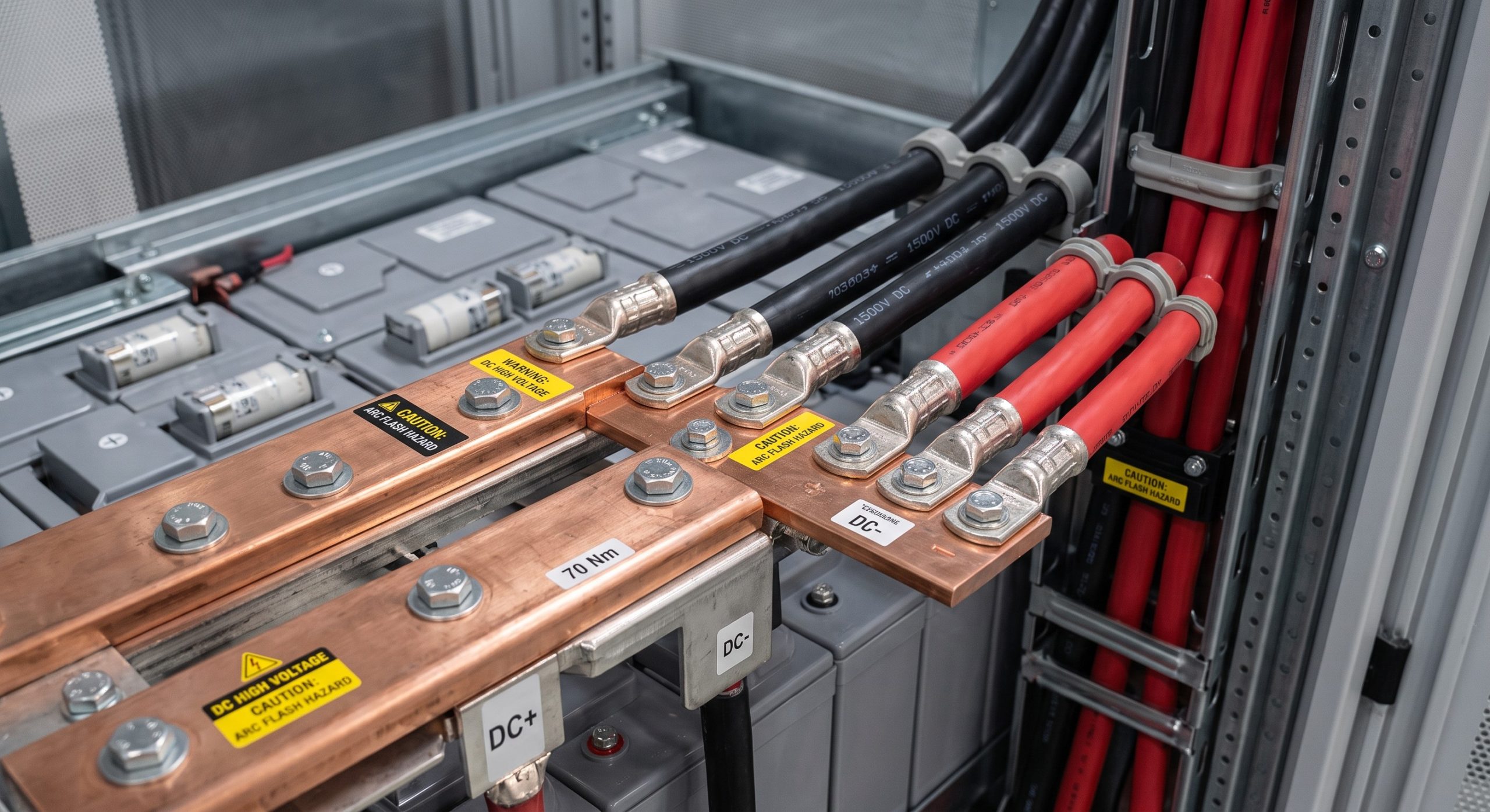
For optimal current carrying capacity and minimal ohmic losses, the common DC busbar is specified as copper with a minimum conductivity of 58 MS/m. Cross-sectional area is selected based on the total parallel current rating, following NEC and IEC 60364 derating factors. Busbar supports are designed to withstand short-circuit electromagnetic forces and are coated with an anti-corrosive tin or silver plating to ensure low contact resistance.
KEY FEATURES
– Balanced Current Distribution: The BMS employs active current balancing algorithms to maintain equal state of charge (SOC) across all parallel clusters. This prevents over-discharge or over-charge of individual units.
– Scalability: The parallel wiring architecture supports the connection of up to 4 battery clusters per PCS DC input, enabling site-specific capacity scaling from 215 kWh to over 1 MWh per system block.
– Fault Isolation: Each cluster is protected by high-speed fuses and the BMS ensures that any cluster-level fault triggers immediate disconnection without disrupting the entire system.
– Communication Integration: All cluster BMS units communicate over a redundant CAN-bus or RS-485 network with the master BMS, providing real-time data on current sharing, temperature, and voltage for complete system oversight.
TECHNICAL SPECIFICATIONS
The following table provides the key electrical and mechanical parameters for parallel wiring hardware and system performance.
| Parameter | Specification |
|---|---|
| Nominal Voltage Range | 600 VDC to 1500 VDC (per cluster) |
| Maximum Parallel Current | Up to 2500 A (combined DC bus) |
| Cluster Voltage Matching Tolerance | +/- 5V DC |
| Busbar Material | High-Conductivity Copper (Tin/Silver Plating) |
| DC Cable Cross-Section (Recommended) | 120 mm² to 240 mm² (depending on current) |
| Maximum Parallel Clusters | 4 units per PCS DC input |
| Communication Protocol | CAN-bus 2.0B / RS-485 |
| Protection | Class II Overvoltage Protection, Integrated Fuses & Contactors |
INDUSTRIAL DEPLOYMENT
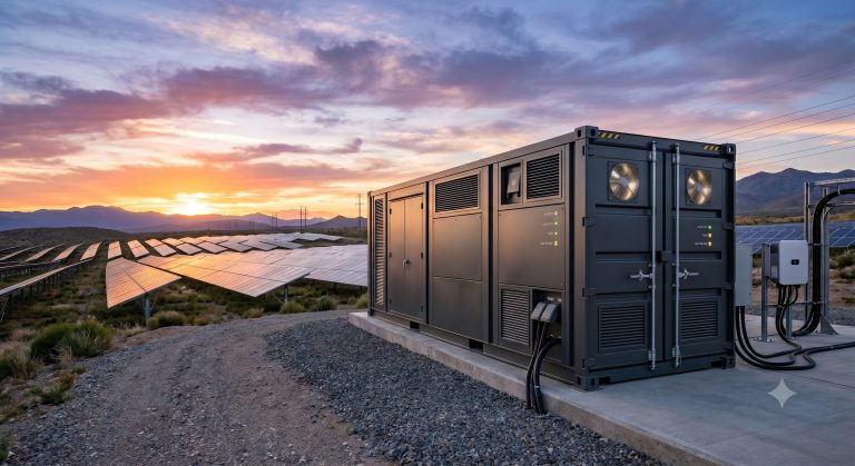
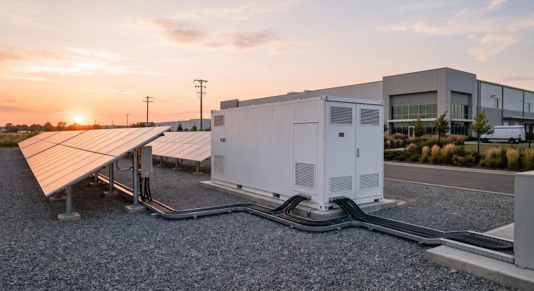
Parallel wiring deployments are ideally suited for industrial peak shaving, solar-plus-storage integration, and EV supercharging buffer applications. The wiring topology must be carefully laid out in the field to minimize cable inductance and voltage drops. For multi-cabinet configurations, the following guidelines apply:
– Cable Routing: DC power cables should be routed in parallel with minimal loop area to reduce radiated emissions and susceptibility to interference. Positive and negative conductors should be run in close proximity, preferably within the same conduit or cable tray.
– Lugging and Torque: All busbar and cable terminations must be torqued to manufacturer-specified values. Loose connections are a primary source of resistance heating and arc flash risk.
– Auxiliary Wiring: Low-voltage communication and auxiliary power cables must be segregated from high-voltage DC conductors to prevent noise coupling. Shielded twisted-pair cables are recommended for communication lines.
– Grounding: A dedicated, low-impedance grounding conductor must connect the metallic chassis of each cluster to the site’s main earthing point. This ensures effective fault clearing and personnel safety.
– Post-Installation Verification: Following installation, a DC insulation resistance test (Megger) and a contact resistance test (Ductor) are required to validate the integrity of all parallel wiring connections.
📥 Download Technical Specification
Click the button below to view or download the full official PDF datasheet.