EQUIPMENT INTRODUCTION
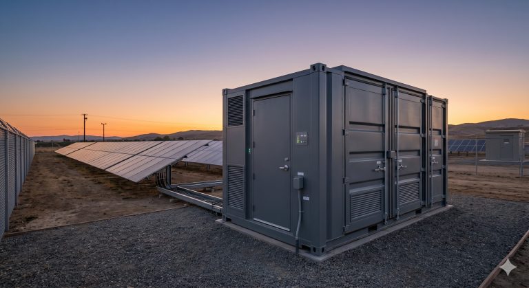
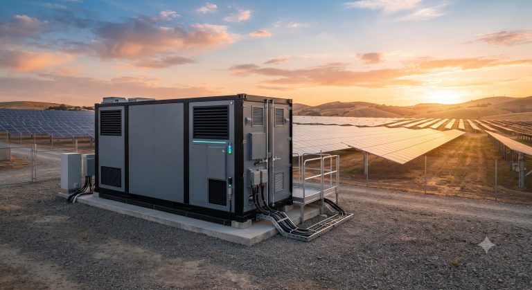
The Battery Module Replacement Procedure is a controlled field-service workflow developed for Tier-1 commercial and industrial battery energy storage systems (BESS). This reference manual defines the mandatory sequence of electrical isolation, thermal stabilization, module extraction, replacement verification, and system recommissioning required to restore a storage cabinet to full operational capacity after a module-level fault or degradation event. The procedure is engineered for field service engineers, commissioning agents, and O&M contractors operating within UL 9540A evaluated enclosures and IEC 62619 compliant battery architectures. Every step is designed to preserve DC bus integrity, maintain BMS data continuity, and eliminate arc-flash or thermal event risk during maintenance windows.
OUTDOOR PAD PREREQUISITES
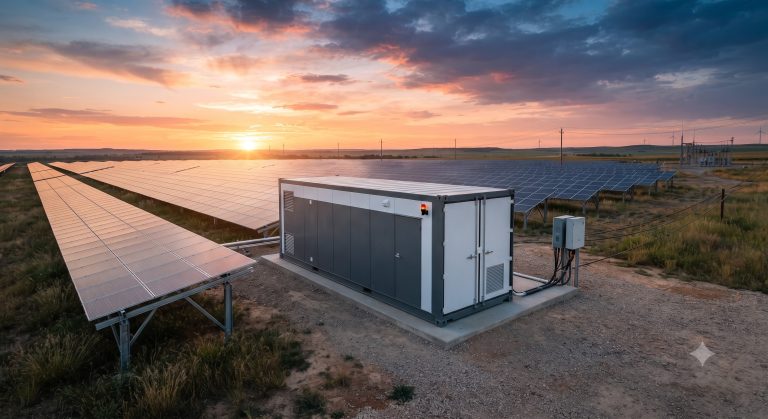
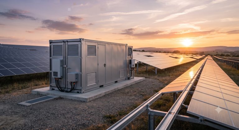
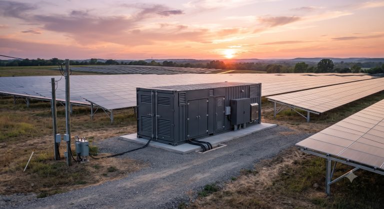
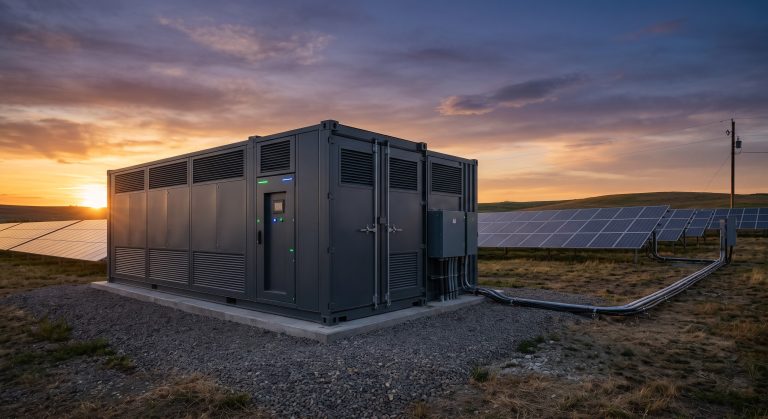
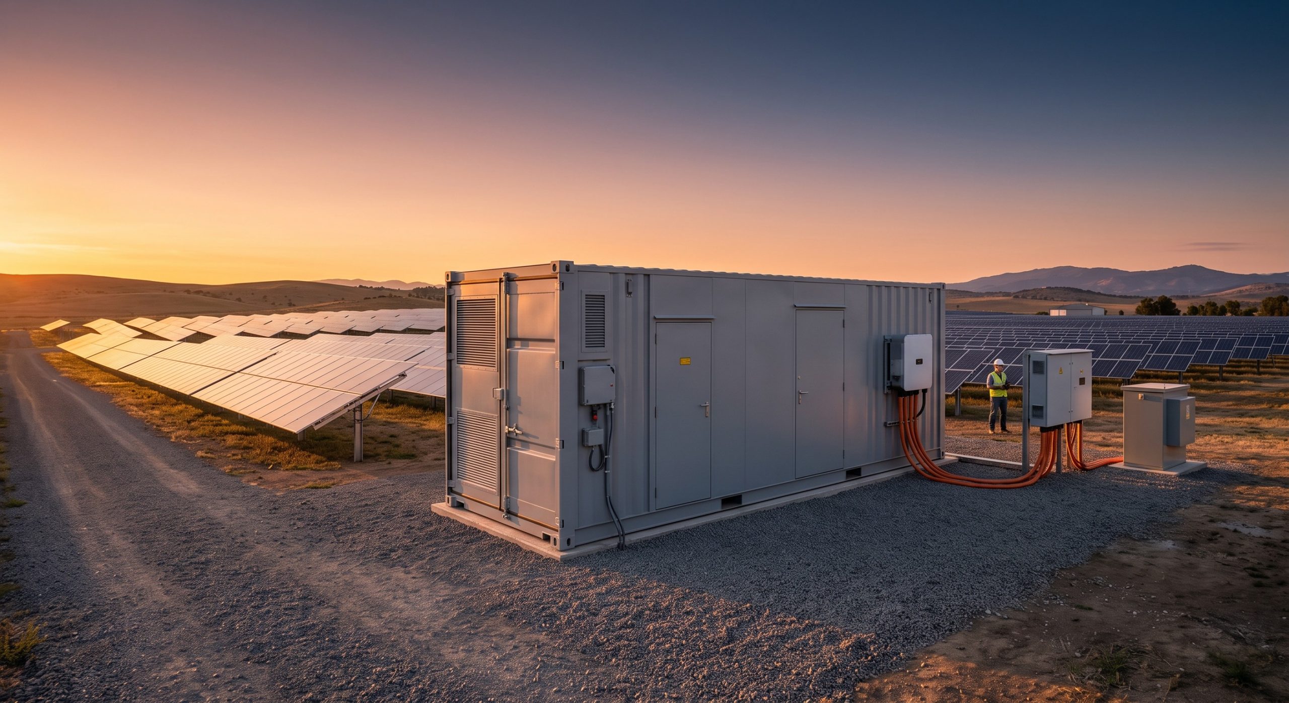
Before any module replacement activity begins, the site must satisfy a defined set of pad-level and environmental prerequisites. The storage cabinet must be de-energized at the AC and DC disconnect points, locked out and tagged out in accordance with NFPA 70E. Ambient temperature must be maintained between -10°C and 45°C, with relative humidity below 85% non-condensing. The pad surface must provide a minimum 1.5-meter clearance perimeter for module handling and cart staging. A calibrated torque wrench, insulated PPE rated to 1000 VDC, replacement module with matched batch code, and BMS configuration laptop must be present. The site EMS must be placed in maintenance mode to prevent remote dispatch commands during the procedure.
BMS BALANCING PROTOCOLS
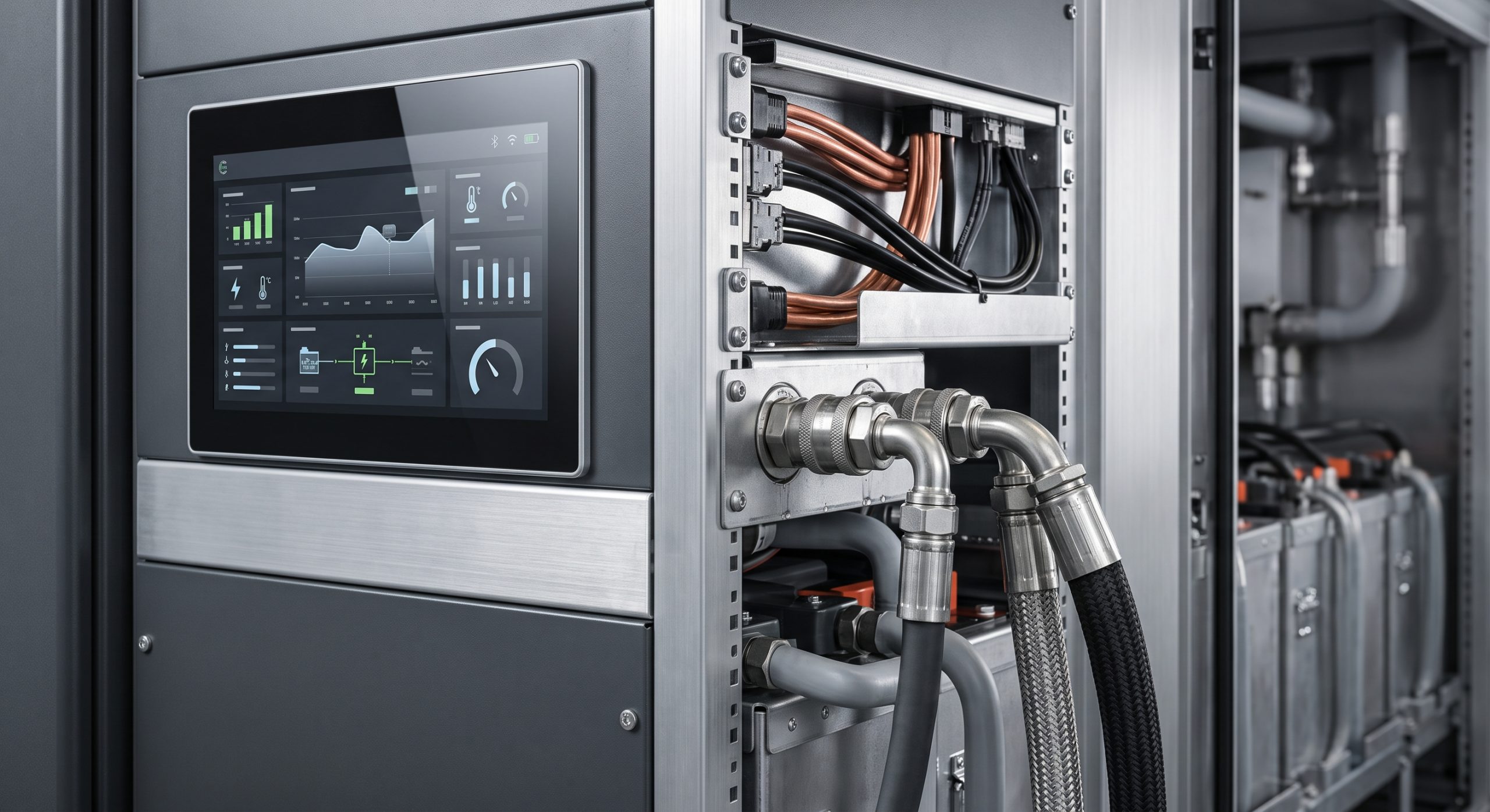
After physical replacement, the new module must be integrated into the existing battery stack through a controlled balancing sequence. The BMS initiates a low-current charge-discharge cycle to align the replacement module state of charge (SOC) with the string average. Voltage delta must converge below 30 mV before the cabinet is returned to service. The active equalization function then maintains cell-level balance across the entire rack. All balancing events are logged in the BMS event register with timestamps and module serial numbers for traceability and warranty validation.
KEY FEATURES
– Hot-Swappable Module Architecture: Rack-level design allows module extraction without dismantling adjacent battery stacks or DC busbar assemblies.
– Serialized BMS Handshake: Every replacement module is automatically authenticated by the string BMS, preventing mismatched chemistry or firmware from entering the power stack.
– Torque-Verified Terminal Interface: Busbar connections require calibrated torque values recorded in the service log to prevent loose-joint thermal runaway precursors.
– Integrated Arc-Flash Suppression: Module disconnect points are rated for live DC operation with reinforced insulation and arc chute geometry.
– Cloud-Synced Service Records: Replacement events are transmitted to the OEM monitoring platform for warranty continuity and fleet health analytics.
VERIFIED SPECS
The module replacement procedure is validated against the following system-level parameters. Replacement duration per module is typically 25 to 40 minutes for a two-person service team. The procedure supports cabinets rated from 215 kWh to 372 kWh per unit. Compatible module formats include 280 Ah and 314 Ah Tier-1 LFP prismatic cells with liquid-cooled cold plate interfaces. All service activities are performed while the remaining strings continue to provide backup power or grid services where the architecture supports string-level isolation.
| Parameter | Specification |
|---|---|
| Nominal Capacity | 215 kWh / 372 kWh per cabinet |
| Cooling Method | Smart Liquid Cooling |
| Cell Chemistry | Tier-1 LFP |
| Module Replacement Time | 25–40 minutes per module (two-person team) |
| BMS Voltage Delta Tolerance | < 30 mV before return to service |
| Compatible Cell Formats | 280 Ah / 314 Ah prismatic LFP |
| Isolation Rating | 1000 VDC live disconnect capability |
| Service Observation Window | 72 hours post-replacement |
| Compliance Basis | UL 9540A, IEC 62619, NFPA 70E |
LOCAL O&M MAINTENANCE LOGIC
The procedure is embedded within a broader local O&M maintenance logic that governs periodic inspection, thermal imaging, insulation resistance testing, and firmware updates. Following module replacement, the site enters a 72-hour observation window during which the EMS monitors cell voltage spread, temperature gradient, and round-trip efficiency deviation. If all parameters remain within tolerance, the cabinet is returned to normal dispatch. If anomalies persist, the BMS escalates to the OEM remote diagnostics team for advanced troubleshooting. This closed-loop service logic ensures that every module replacement culminates in a verified, documented, and warranty-compliant restoration of the energy storage asset.
📥 Download Technical Specification
Click the button below to view or download the full official PDF datasheet.