How Does the BMS Communicate with the Power Conversion System (PCS)?
The Battery Management System (BMS) communicates with the Power Conversion System (PCS) primarily over CAN bus or Modbus TCP/RTU, exchanging real-time state-of-charge (SOC), voltage, current, temperature and fault data so the PCS can regulate charge/discharge power safely. In a commercial BESS, this link is the nervous system of the plant: the BMS acts as the battery’s guardian, while the PCS acts as the muscle that converts DC power to grid-compliant AC. When this communication is fast, deterministic and redundant, the system achieves stable grid-tie operation, seamless off-grid switching and long battery life. This FAQ answers the highest-intent pre-sales and post-sales questions plant engineers, EPCs and procurement teams ask about BESS integration.
Frequently Asked Questions
- Q1: Which communication protocols does the BMS use to talk to the PCS?
- The BMS typically communicates with the PCS via CAN bus (CAN 2.0B, J1939) or Modbus TCP/RTU over RS-485 and Ethernet. CAN bus is preferred for high-speed, deterministic cell-level data such as SOC, state-of-health (SOH), pack voltage, current limits and fault flags, while Modbus TCP is common for SCADA and EMS integration. Most Tier-1 PCS platforms support both, and a well-designed BESS uses a redundant link so the PCS can fall back to safe mode if one channel drops.
- Q2: What battery chemistry and cycle life should I specify for a commercial BESS?
- The standard chemistry for commercial BESS is Tier-1 LFP (lithium iron phosphate), delivering 6,000–8,000 cycles at 80% depth of discharge (DoD). LFP is preferred over NMC for stationary storage because of its superior thermal stability, longer cycle life and lower levelized cost of storage (LCOS). At 80% DoD and one cycle per day, an 8,000-cycle LFP pack supports roughly 20+ years of calendar life, though performance warranties are typically written for 10 years or a defined MWh throughput.
- Q3: How do liquid cooling and thermal runaway prevention work together?
- Liquid cooling maintains cell temperatures within a narrow band, typically 25°C ±3°C, which slows degradation and prevents thermal runaway propagation. A multi-tier safety architecture combines liquid-cooled plates, cell-level fuses, pack-level gas and smoke detection, per-rack isolation and an aerosol or NOVEC 1230 fire suppression system. The BMS continuously monitors cell voltage and temperature; if it detects abnormal rise, it commands the PCS to stop charge/discharge and triggers the fire suppression sequence before a runaway can propagate between modules.
- Q4: Can the BESS scale from a single cabinet to a multi-MWh plant?
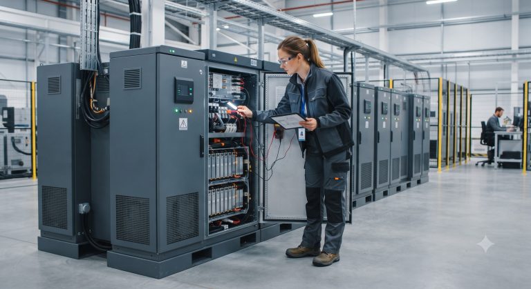
- Yes. A standard modular BESS scales from a single 100–215 kWh cabinet to multi-MWh plants by paralleling cabinets on a shared DC busbar or AC-coupled architecture. The BMS uses a master-slave topology: each rack has a slave BMS reporting to a master BMS, which aggregates data and communicates with the PCS and EMS. Because the PCS sees the battery as one virtual pack, expansion is transparent as long as DC voltage windows and communication addresses are configured correctly.
- Q5: How is the BMS monitored after commissioning, and what data does it expose?
- The BMS exposes real-time SOC, SOH, cell voltages, temperatures, current limits and fault codes to the EMS and a cloud monitoring platform over Modbus TCP, SNMP or MQTT. Post-sales monitoring typically includes a web dashboard and mobile alerts for cell imbalance, over-temperature, insulation faults and communication loss. Remote firmware updates and diagnostic logs let support engineers troubleshoot without a site visit, which is critical for distributed C&I fleets.
- Q6: What is the difference between grid-tie and off-grid configuration for the PCS?
- In grid-tie mode, the PCS synchronizes to the utility waveform and performs peak shaving, demand response and arbitrage, while in off-grid mode it forms its own voltage and frequency reference for islanded loads. A bidirectional PCS with seamless transfer can switch between modes in under 20 ms, keeping critical loads online during a grid outage. The BMS must be configured with different SOC reserve floors for each mode so the battery always has enough energy to ride through a transition.
- Q7: How do I calculate ROI, peak shaving savings and LCOE for a BESS project?
- ROI is calculated from annual peak shaving savings plus arbitrage revenue minus O&M and financing costs, divided by installed capex. A typical C&I BESS in a high-demand-charge market achieves payback in 4–7 years. LCOE is capex plus lifetime O&M divided by total lifetime MWh discharged; with LFP at 8,000 cycles and 90% round-trip efficiency, LCOS often lands between $0.05 and $0.10 per kWh, depending on cycling frequency and electricity tariffs.
- Q8: What certifications and interconnection standards should the BESS meet?
- A commercial BESS should carry UL 9540 (system), UL 9540A (thermal runaway test), IEC 62619 (cell safety), IEC 62477 (PCS safety) and CE marking for EU deployment. Grid interconnection additionally requires IEEE 1547 or UL 1741 SB for the PCS in North America, and local grid-code compliance such as VDE-AR-N 4105 in Germany. These certifications are non-negotiable for permitting, insurance and utility approval, so buyers should request test reports during procurement.