COMMERCIAL SYSTEMS ENGINEERING REFERENCE MANUAL: ENERGY STORAGE INVERTER INTEGRATION
EXECUTIVE SUMMARY
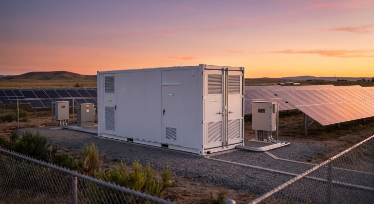
This document serves as the definitive technical reference for the integration of the advanced energy storage inverter (PCS) within the broader Battery Energy Storage System (BESS) architecture. Designed for system integrators, EPC firms, and facility engineers, this manual outlines the hardware interfaces, communication protocols, cooling system requirements, and safety interlocks necessary for seamless, high-performance deployment. Our modular, Tier-1 LFP-based platform ensures reliable grid stabilization, peak shaving, and PV self-consumption optimization for commercial and industrial (C&I) applications, delivering superior round-trip efficiency and a proven lifecycle that minimizes total cost of ownership.
SYSTEM ARCHITECTURE & SAFETY
The inverter integration model is predicated on a highly redundant, fail-safe architecture. The bi-directional PCS acts as the central energy gateway, orchestrating DC-to-AC and AC-to-DC conversion with a peak efficiency exceeding 98.5%. The architecture employs a three-level topology that significantly reduces harmonic distortion (THDi < 3%) and enables seamless transition between grid-connected and islanding modes. Safety is architected at every level, featuring integrated DC circuit breakers, rapid shutdown functionality, and a dedicated battery management system (BMS) that communicates directly with the PCS via high-speed CAN bus. This closed-loop control ensures cell voltage and temperature are maintained within safe operating limits, with active anti-islanding protection compliant with local grid codes. The system is housed in an IP55-rated, corrosion-resistant outdoor enclosure, ensuring reliable operation in harsh environmental conditions. KEY FEATURES - Seamless Grid Interfacing: Supports both grid-tied and off-grid (island) operation, enabling uninterrupted power supply (UPS) functionality with a < 20 ms transfer time. - Intelligent Thermal Management: Integrated liquid cooling loop maintains optimal cell temperature, enhancing battery life and ensuring consistent power output across ambient temperature ranges from -30°C to +55°C. - Scalable Parallel Architecture: Supports flexible capacity expansion by allowing up to 10 units to be paralleled on the AC and DC bus, achieving multi-MWh storage capacity without the need for complex external synchronization. - Advanced Control Algorithm: Proprietary EMS coordination enables peak shaving, load shifting, and PV forecast smoothing, directly interfacing with standard Modbus TCP/IP and IEC 61850 protocols. - High Overload Capability: Capable of delivering 110% overload for 10 minutes, providing robust support for motor startups and high-inrush industrial loads. - Black Start Capability: Integrated auxiliary power supply enables autonomous system restart from a complete grid outage, a critical feature for micro-grid applications. COMPLIANCE & STANDARDS The integrated inverter solution is certified to meet the most stringent international standards, providing a clear path to grid interconnection approval. The system holds full certification for UL 1741 SA and IEEE 1547 for grid interconnection in North America, guaranteeing compliance with anti-islanding and power quality requirements. Globally, the unit meets IEC 62109-1 and IEC 62109-2 for safety, IEC 61000-6-2 and IEC 61000-6-4 for electromagnetic compatibility, and has successfully passed the rigorous UL 9540A thermal runaway propagation test. Additionally, all components are fully RoHS and REACH compliant, underscoring our commitment to sustainable manufacturing practices. TECHNICAL SPECIFICATIONS The table below details the core electrical, mechanical, and environmental specifications for the integrated inverter and storage system. These parameters are validated under standard test conditions (STC) at 25°C ambient and 100% rated power, with a nominal DC input voltage of 800V – 1500V.
| Parameter | Specification |
|---|---|
| AC Output Power (Rated) | 500 kVA (at 25°C) |
| AC Grid Voltage / Frequency | 480V / 60Hz (3P4W) |
| Battery Voltage Range | 800 VDC – 1500 VDC |
| Max. DC Input Current | 1200 A |
| Peak Efficiency | > 98.5% |
| Cooling Method | Smart Liquid Cooling (Water/Glycol) |
| Operating Temperature Range | -30°C to +55°C (derating >45°C) |
| Ingress Protection | IP55 (NEMA 3R) |
| Standard Communication | Modbus TCP/IP, IEC 61850, CAN |
| Dimensions (W x D x H) | 2400 mm x 1300 mm x 2500 mm |
INDUSTRIAL DEPLOYMENT
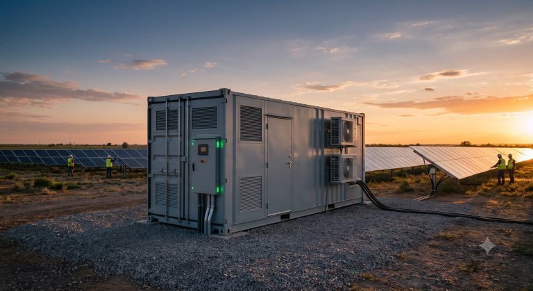
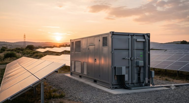
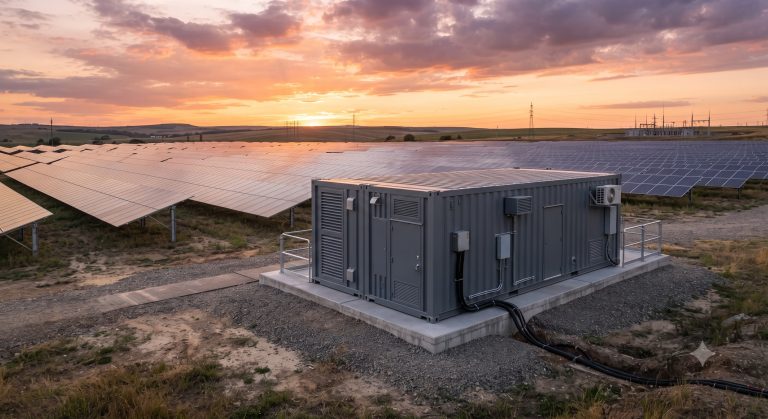
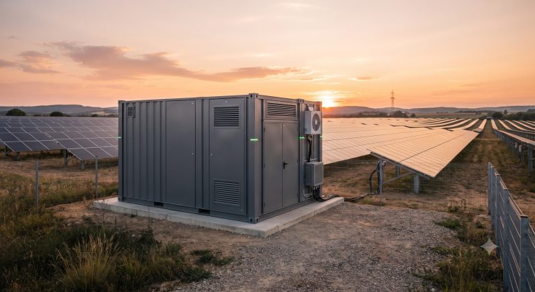
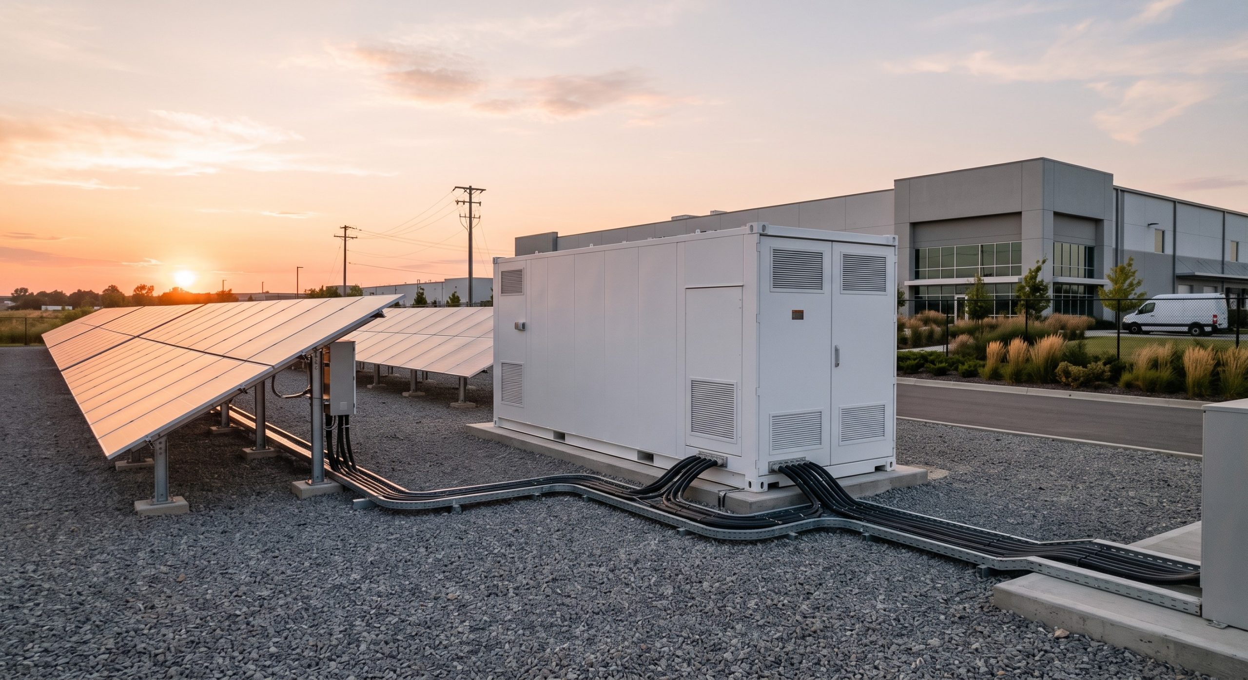
Integration of this inverter platform into an operational facility requires adherence to specific engineering guidelines to ensure maximum performance and longevity. The physical installation must be conducted on a level, non-combustible foundation, with a minimum clearance of 1 meter from the front for access and 0.5 meters from the side for adequate ventilation. AC and DC cable glands are located on the lower portion of the unit to facilitate standard top-entry or bottom-entry conduit runs. The liquid cooling interface requires connection to a closed-loop chiller system or a dry cooler, with a recommended glycol-to-water ratio of 30:70. For network integration, the system provides dual RJ-45 Ethernet ports for redundancy, with an optional cellular modem for remote monitoring via our cloud-based EMS platform. Detailed electrical and mechanical mounting schematics are provided in the full installation manual, illustrating the exact busbar dimensions and torque specifications for termination. An illustrative deployment topology is shown below, highlighting the integration with PV arrays and the facility’s main switchgear.

📥 Download Technical Specification
Click the button below to view or download the full official PDF datasheet.