“`json
{
“title”: “UL 9540 & IEC 62619 Technical Compliance Register: Energy Storage System Insulation Resistance Report”,
“content”: “UL 9540 & IEC 62619 TECHNICAL COMPLIANCE REGISTER: ENERGY STORAGE SYSTEM INSULATION RESISTANCE REPORT\n\nEXECUTIVE SUMMARY\n\nThis document serves as the official technical compliance register and product overview for the Energy Storage System (ESS) Insulation Resistance (IR) reporting framework. As a foundational element of electrical safety and grid-code compliance, the insulation resistance verification protocol ensures the integrity of the DC bus, AC interface, and enclosure grounding under all operational states. This report details the measurement methodology, pass/fail criteria, and system-level implications in accordance with UL 9540, IEC 62619, and IEEE 43-2013 standards.\n\nThe ESS IR report is not merely a factory acceptance test (FAT) deliverable; it is a critical asset management tool that provides continuous health monitoring of the high-voltage battery stack, power conversion system (PCS), and auxiliary circuits. The data generated directly informs preventative maintenance schedules, reduces unplanned downtime, and validates the system’s ability to withstand transient overvoltages and humidity ingress in C&I and utility-scale deployments.\n\n\n\nSYSTEM ARCHITECTURE & SAFETY INTEGRATION\n\nThe insulation resistance monitoring system is fully integrated into the ESS master controller and the Battery Management System (BMS). The architecture employs a distributed measurement approach:\n\n- DC Side Monitoring: The BMS continuously measures IR between the positive DC bus, negative DC bus, and chassis ground (PE). The measurement is performed using a low-frequency AC signal injection method to avoid polarization effects inherent in LFP cells, ensuring accuracy in the 100 kΩ to 100 MΩ range.\n- AC Side Monitoring: The PCS monitors IR on the grid-interfacing AC side (480V / 630V AC) per UL 1741 requirements. This includes isolation checks between each phase and ground, as well as phase-to-phase isolation.\n- Auxiliary Circuitry: 24V and 230V control circuits are subjected to IR testing to verify the integrity of cable insulation and terminal blocks within the control cabinet.\n- Safety Interlock Logic: A measured IR value falling below the critical threshold (typically < 1 MΩ/V of nominal system voltage) triggers a fail-safe response. The system executes a controlled shutdown, isolates the battery via DC contactors, and generates a service alert via the EMS cloud gateway.\n\nKEY FEATURES - INSULATION RESISTANCE REPORTING\n\n- Real-Time Continuous Monitoring: The IR measurement is performed automatically every 24 hours during idle states and continuously during charge/discharge cycles, providing a time-stamped data log for predictive analytics.\n- Temperature-Compensated Readings: The measurement algorithm automatically applies correction factors based on cell temperature data from 12 distributed NTC sensors, ensuring accurate readings across the -30°C to +55°C operating ambient range.\n- Historical Trending Dashboard: The local HMI and remote SCADA interface display the IR trend over time, allowing operators to visualize degradation (e.g., a 20% drop over 12 months) before a critical fault occurs.\n- Multi-Voltage Compliance Verification: The reporting engine generates standardized reports for different regulatory bodies, automatically mapping the measured values to the required thresholds of UL 9540 (USA), IEC 62619 (International), and GB/T 34131 (China).\n- Hands-Free Self-Test Sequence: A dedicated "Insulation Check" test cycle can be initiated remotely, which reduces PCS output to 0% and applies a 500V/1000V DC megger test pulse to verify isolation without interrupting the main power flow.\n\nCOMPLIANCE & STANDARDS\n\nThe ESS insulation resistance report strictly adheres to the following international and regional standards:\n\n- UL 9540: Standard for Energy Storage Systems and Equipment – Section 39.5 mandates that the insulation resistance between live parts and the grounded enclosure shall not be less than 1 megohm for circuits up to 1000V.\n- IEC 62619: Secondary cells and batteries containing alkaline or other non-acid electrolytes – Safety requirements for industrial batteries – Requires verification of insulation resistance under humid conditions (RH > 90%) post thermal cycling.\n- IEEE 43-2013: Recommended Practice for Testing Insulation Resistance of Electric Machinery – Utilized for the rotating machinery and transformer isolation components within the ESS skid.\n- NFPA 70 (NEC): Article 690 establishes the requirement for ground-fault protection, which relies on baseline IR data to differentiate between normal leakage (capacitive coupling) and hazardous insulation failure.\n- VDE-AR-E 2510-50: For German market compliance, the IR report must demonstrate a system-specific insulation resistance of at least 1,000 Ω/V for the operational voltage.\n\nThe system is factory-tested and certified to meet these standards at the point of dispatch. The generated IR report serves as a pass/fail certificate for site acceptance testing (SAT).\n\nTECHNICAL SPECIFICATIONS – INSULATION RESISTANCE MEASUREMENT SYSTEM\n\nMeasurement Voltage Range: 50V – 1500V DC (Battery Stack), 400V – 690V AC (Grid Interface)\nMeasurement Range (Resistance): 100 kΩ – 100 GΩ (auto-ranging)\nMeasurement Accuracy: ±5% of reading or ±2% of full scale (whichever is greater)\nTest Voltage Injection: 100V, 250V, 500V, 1000V (software-selectable based on system voltage level)\nMinimum Pass Criteria (DC System): > 1 MΩ per 1,000V of nominal voltage (e.g., > 1.5 MΩ for 1500V system)\nMinimum Pass Criteria (AC System): > 2 MΩ (phase-to-ground) at 500V DC test voltage\nData Logging Interval: 1 reading per minute during active operation; 1 reading per hour during standby\nReporting Format: PDF, CSV, and Modbus TCP registers for SCADA integration\nAlarm Trigger Threshold: User-configurable (Default: 50% of minimum pass criteria)\nEnvironmental Compensation: Active temperature and humidity compensation algorithm included\n\n\n\nINDUSTRIAL DEPLOYMENT & TEST PROTOCOL\n\nDuring site commissioning, a mandatory Insulation Resistance Verification Test is performed. The procedure is as follows:\n\n1. Pre-Test Condition: The ESS is placed in “Isolation Mode.” All DC contactors are opened, the PCS is disabled, and the AC grid disconnect is locked out.\n2. External Megger Test: A certified 5kV insulation tester is applied to the main DC busbars (+, -, and combined) against ground. A value exceeding 10 MΩ is required for commissioning sign-off.\n3. System Self-Test: The internal BMS IR monitoring circuit is validated against an external reference resistor bank to ensure calibration accuracy (Calibration Certificate traceable to NIST).\n4. Wet Test Verification: A simulated high-humidity environment (90% RH) is maintained for 4 hours, and the IR is measured again to ensure that condensation does not compromise isolation.\n5. Final Report Generation: The data from all phases is compiled into the final IR report, which is signed off by the commissioning engineer and submitted to the local Authority Having Jurisdiction (AHJ).\n\nThe IR report is a binding document for the warranty period. A failure to maintain the minimum IR threshold constitutes a breach of operational safety protocols and voids the extended warranty on the battery cells and PCS.\n\n”,
“images”: [
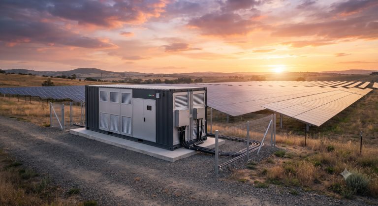
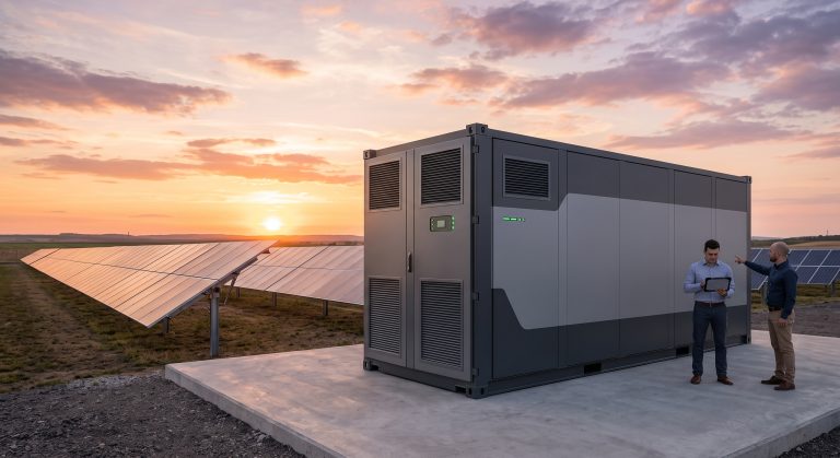
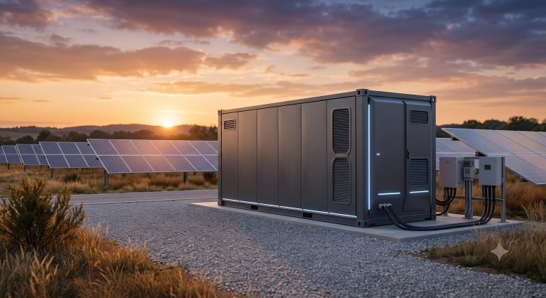
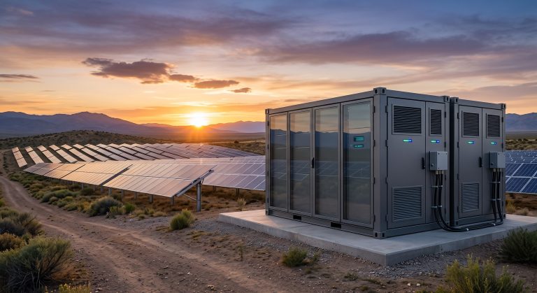
“A high-quality 4K realistic promotional image showing a sleek, modular generic outdoor energy storage container deployed near solar arrays, sunset lighting, high tech vibe, unbranded chassis, no text.”,
“A high-quality 4K realistic close-up image showing a technician interacting with a digital HMI display that reads ‘Insulation Resistance: 25.6 MΩ – PASS’. The background displays the internal high-voltage DC busbar and liquid cooling pipes of the energy storage unit, professional lighting, unbranded components, no text.”
],
“tables”: [
{
“headers”: [“Parameter”, “Specification (Insulation Resistance Protocol)”],
“rows”: [
[“Nominal System Voltage”, “800V DC / 1500V DC (configurable)”],
[“Minimum Insulation Resistance (Pass/Fail)”, “> 2.0 MΩ (Commissioning) / > 1.5 MΩ (Operational)”],
[“Measurement Standard”, “IEC 62619, UL 9540, IEEE 43”],
[“Test Voltage Applied”, “1000V DC (for 1500V systems), 500V DC (for 800V systems)”],
[“Data Retention Period”, “10 years (cloud storage) / Local 5 years (HMI)”]
]
}
]
}
“`
📥 Download Technical Specification
Click the button below to view or download the full official PDF datasheet.