Introduction: The Thermal Frontier of Commercial Energy Storage
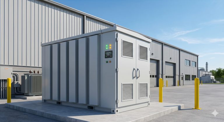
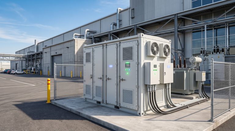
As commercial and industrial (C&I) facilities worldwide accelerate their transition toward energy independence, the liquid-cooled container ESS has emerged as the definitive architecture for high-density, utility-scale behind-the-meter storage. Unlike traditional air-cooled systems that struggle with thermal gradients and cell imbalance, liquid-cooled containerized battery energy storage systems (BESS) leverage advanced coolant circulation to maintain optimal operating temperatures across thousands of lithium iron phosphate (LFP) cells, ensuring superior round-trip efficiency and extended cycle life. For C&I project developers, system integrators, and facility managers, understanding the engineering nuances of liquid-cooled container ESS is critical for optimizing peak-shaving returns, participating in demand response programs, and meeting stringent safety certifications like IEC 62619 and UL 9540.
Core System Architecture & PCS Integration Dynamics
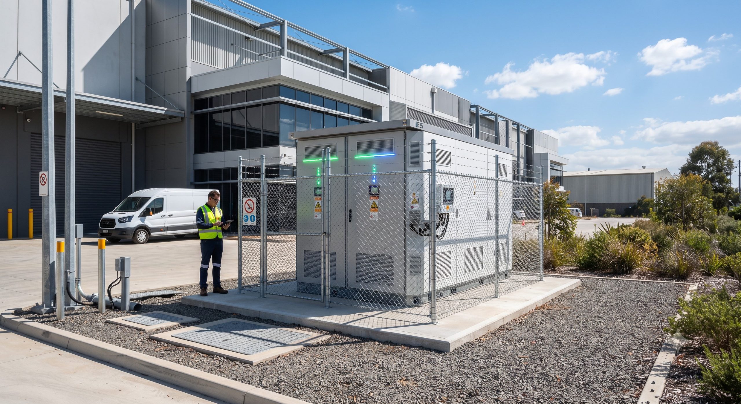
The foundation of any high-performance liquid-cooled container ESS lies in the symbiotic relationship between its battery racks, bi-directional power conversion system (PCS), and intelligent battery management system (BMS). In modern systems, the PCS employs a modular, multi-level topology that achieves conversion efficiencies exceeding 98.5%, with the ability to perform seamless grid-forming and grid-following transitions. The integration of liquid cooling directly impacts power electronics reliability; by maintaining IGBT junction temperatures below 85°C, the system sustains rated AC output even under 1C charge/discharge cycles. The BMS continuously monitors cell-level voltage, temperature, and impedance, utilizing passive or active balancing circuits to correct state-of-charge (SoC) discrepancies, which is paramount for maintaining the liquid-cooled container ESS health over its 15+ year design life.
Liquid Cooling vs. Air Cooling: A Thermal Efficiency Paradigm
While air-cooled ESS solutions rely on forced convection to dissipate heat, they often create temperature differentials of up to 8-10°C between cells, accelerating degradation and reducing usable capacity. In contrast, the liquid-cooled container ESS utilizes dielectric coolant or deionized water-glycol mixtures circulated through cold plates adjacent to each battery module. This liquid thermal management system achieves cell-to-cell temperature uniformity within ±1.5°C, dramatically improving the depth of discharge (DoD) capability. For instance, at a 90% DoD, liquid-cooled configurations routinely achieve >8000 full cycles before reaching 80% state of health (SOH), a >30% improvement over equivalent air-cooled alternatives. This uniformity is essential for high-capacity containerized ESS deployed in hot climates or within steel manufacturing plants, where ambient temperatures frequently exceed 40°C.
Technical Specifications & Performance Data
All high-quality liquid-cooled container ESS solutions are validated against rigorous international standards. The table below outlines the primary specifications found in Tier-1 systems from global battery manufacturers. These metrics directly influence project financial modeling, particularly the levelized cost of storage (LCOE).
| Key Parameter | Technical Specification |
|---|---|
| Battery Chemistry | Tier-1 LFP (Lithium Iron Phosphate) with active balancing |
| System Capacity | Ranges from 1MWh to 5MWh per 20ft/40ft container |
| Round-trip Efficiency | 92% – 94% (AC-to-AC, measured at 25°C nominal) |
| Cycle Life | >8000 cycles @ 90% DoD with ≤80% SOH retention |
| Thermal Control | Liquid-cooled (Water/Glycol) with ±1.5°C cell uniformity |
| Safety & Compliance | IEC 62619, UL 9540 (System), UN38.3 (Cells), CE |
Safety, Compliance, and Fire Suppression Systems
Safety is non-negotiable in energy storage, and a certified liquid-cooled container ESS incorporates multi-layered protection. Beyond the passive fail-safes within the LFP chemistry, active protection includes per-module aerosol fire suppression, pressure relief vents, and a dedicated gas detection system that automatically triggers ventilation. The container structure itself meets UL 9540A thermal runaway propagation test requirements, ensuring that a single cell failure does not cascade. International shipping compliance, guided by UN38.3, confirms the battery modules are safe for transport, while system-level certification under IEC 62619 validates the design’s robustness for stationary applications. This compliance framework not only reduces insurance premiums but also streamlines grid interconnection permitting for C&I projects.
Commercial ROI: Total Cost of Ownership & Grid Support Strategies
For procurement managers and financial directors, the adoption of a liquid-cooled container ESS is an exercise in maximizing the Net Present Value (NPV) of energy assets. The enhanced cycle life and high round-trip efficiency (typically 92-94% AC-to-AC) directly translate to lower amortized costs per MWh. A 2MW/4MWh liquid-cooled system, when deployed for peak shaving in regions with high demand charges, can reduce peak demand by 80-90%, offering payback periods between 3.5 and 5 years depending on utility rate structures. Furthermore, the system’s rapid response capability (under 50ms) enables participation in grid frequency regulation markets, adding a lucrative revenue stream. Including intelligent Energy Management System (EMS) with VPP (Virtual Power Plant) readiness ensures the liquid-cooled container ESS can aggregate with other distributed energy resources to trade in wholesale markets, significantly improving the business case over a standard 10-year operational window.
Deployment Scenarios & Real-World Project Integration
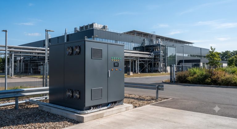
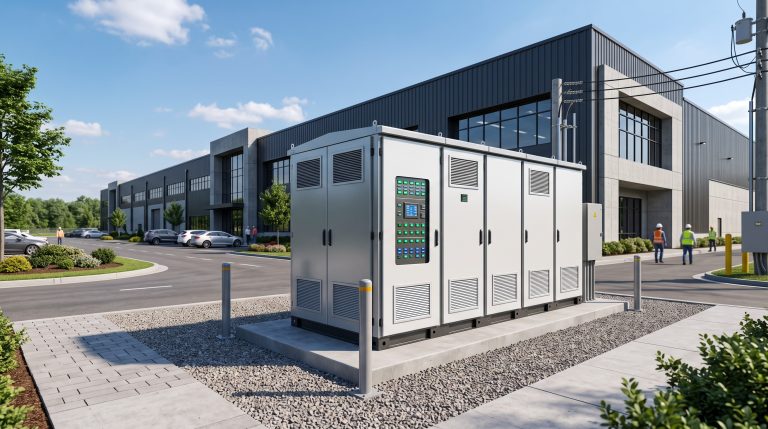
The modular and compact footprint of the liquid-cooled container ESS (typically a 20-foot or 40-foot container housing up to 5MWh of capacity) makes it highly versatile for various C&I verticals. Key deployment scenarios include:
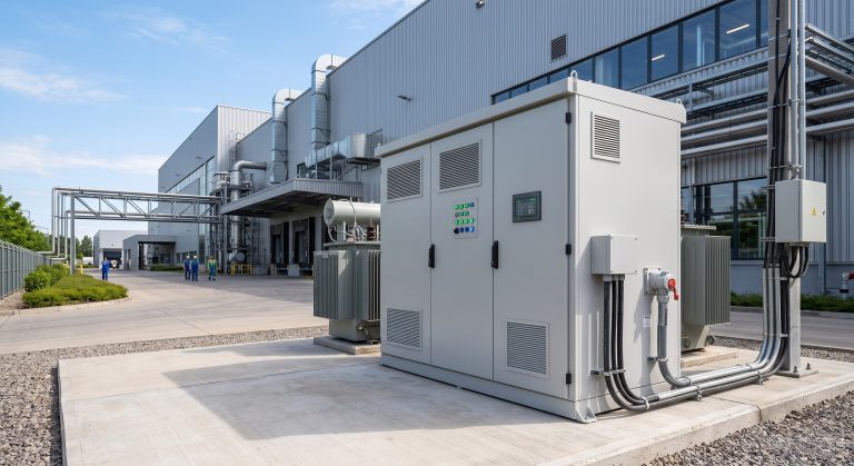
- Industrial Parks & Manufacturing: Pairing with onsite solar PV to mitigate production schedule-related demand spikes.
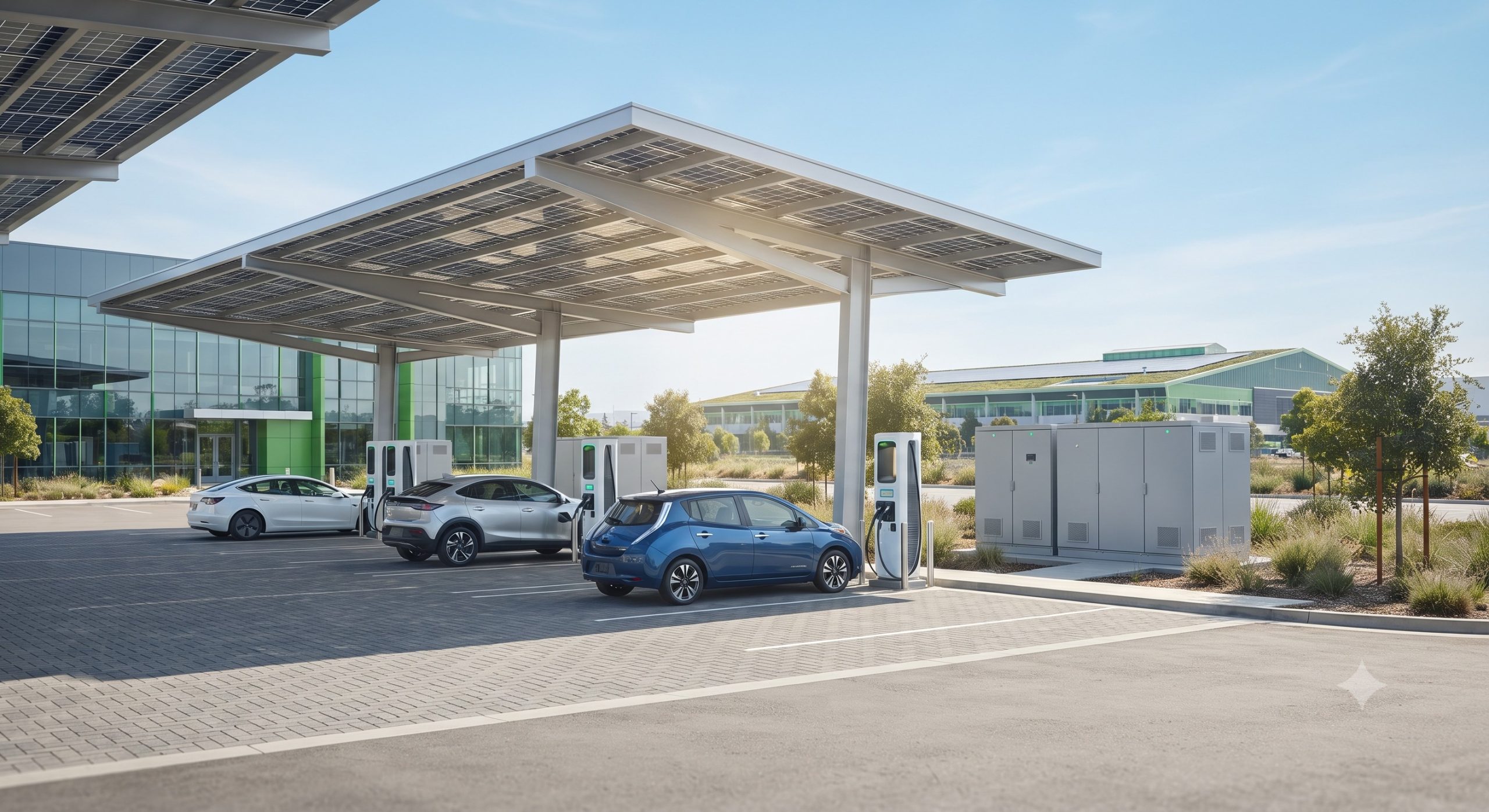
- EV Supercharging Stations: Utilized as a PV-Storage-Charging hub to buffer grid constraints and facilitate ultra-fast 350kW EV chargers, stabilizing the local grid.
- Diesel Generator Replacement: In remote micro-grids, offering silent, emission-free backup power with instantaneous black-start capabilities.
- Data Centers: Providing reliable backup and peak shaving while ensuring that the thermal management system does not compromise the facility’s cooling load.
Conclusion: The Strategic Imperative of Liquid-Cooled Container ESS
As C&I energy managers face increasing pressure to decarbonize operations and stabilize volatile energy costs, the liquid-cooled container ESS stands as a proven, technologically mature solution. Its advanced liquid thermal management, coupled with Tier-1 LFP cells and smart grid-interactive controls, ensures not only unparalleled safety and performance but also a compelling ROI driven by long cycle life and high operational efficiency. When sourcing a liquid-cooled container ESS, prioritize vendors that offer transparent data on cell matching, demonstrated compliance with UL 9540 and IEC 62619, and a comprehensive warranty that guarantees capacity retention over the lifecycle. The future of commercial energy storage is cool, contained, and contingent on liquid cooling.