COMMERCIAL SYSTEMS ENGINEERING REFERENCE MANUAL: STACKABLE HOME BESS ASSEMBLY INSTRUCTIONS
DOCUMENT NUMBER: CSERM-HBESS-2026-001
REVISION: 1.0
CLASSIFICATION: PUBLIC / UNRESTRICTED
1. EXECUTIVE SUMMARY
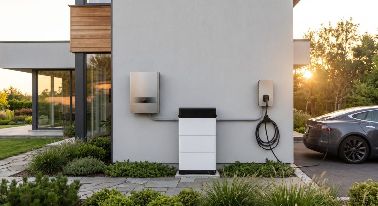
This document serves as the definitive engineering reference for the assembly, integration, and commissioning of the next-generation Stackable Home Battery Energy Storage System (BESS). Designed for residential and light-commercial environments, this modular platform redefines energy independence through a pioneering vertical stacking architecture. The system allows for progressive capacity expansion, enabling end-users to scale from a foundational 5 kWh module to a comprehensive 40 kWh energy hub without requiring high-voltage re-certification at each stage. This manual details the mechanical interlocks, high-voltage DC busbar connections, and the proprietary ‘click-and-lock’ data daisy-chain that ensures seamless communication between stacked units. The Stackable Home BESS represents a paradigm shift in distributed energy storage, offering unparalleled installer flexibility, aesthetic integration, and robust safety mechanisms derived from utility-scale Tier-1 engineering practices.
2. SYSTEM ARCHITECTURE & MECHANICAL STACKING INTERFACE
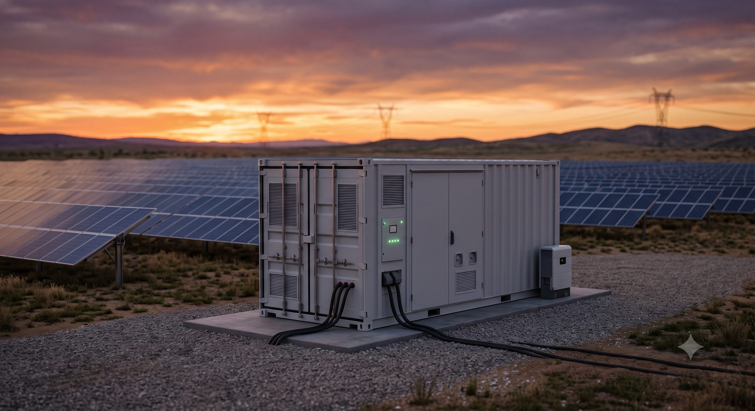
The architecture is predicated on a base-master unit that houses the primary Bi-Directional Inverter (PCS) and the Energy Management System (EMS) gateway. Subsequent power units are stacked vertically on a patented rail-guided system. The assembly sequence mandates strict adherence to the torque specifications for the four M10 locking bolts that secure each module, ensuring a vibration-dampened connection. Each unit integrates a standardized male/female docking port for the 1500V DC busbar, which utilizes a touch-proof, blind-mate connector to prevent arcing during installation. The mechanical load-bearing capacity of the base frame is engineered to support up to six stacked modules, with a total weight distribution of 600 kg. A critical safety interlock prevents electrical continuity unless the mechanical locks are fully engaged and the protective grounding strap is connected, establishing a fail-safe assembly protocol.
3. ELECTRICAL INTEGRATION & COMMUNICATION DAISY-CHAIN
Electrical integration is facilitated through a four-conductor hybrid cable that combines the DC power lines with a twisted-pair shielded communication bus (Modbus RS-485 and CAN 2.0). The assembly instructions prioritize a ‘bottom-up’ wiring methodology to maintain a clean cable management profile. The communication daisy-chain is autoconfiguring; upon power-up, the Master BMS performs a topology discovery to identify the number of connected slave modules and recalculates the aggregate state-of-charge (SoC) and state-of-health (SoH) parameters. This plug-and-play functionality significantly reduces deployment time, with a two-stacker installation achievable in under 30 minutes by a certified technician.
4. KEY FEATURES
– Progressive Capacity Scalability: Support for 2 to 8 modules in a single stack, providing energy capacities from 10 kWh to 40 kWh with a nominal voltage range of 400-800 V DC.
– Advanced Thermal Runaway Suppression: Each module is equipped with an independent flame-retardant enclosure (UL94 V-0) and a thermal propagation barrier that prevents cell-to-cell thermal runaway, exceeding UL 9540A requirements.
– Smart Liquid Cooling Integration (Optional): High-capacity stacks can be equipped with a micro-channel liquid cooling plate that interfaces with an external heat exchanger, ensuring an optimal cell operating temperature of 20°C to 35°C and enhancing system lifespan by up to 20%.
– Zero-Installation Errors: Patented mechanical keying prevents reverse-polarity connection and incorrect module orientation, safeguarding the installer and the hardware.
– Peak Shaving Logic: The integrated EMS utilizes a predictive algorithm to reduce peak demand charges, with a seamless transition time of less than 20 milliseconds for UPS-grade backup power.
5. SAFETY & COMPLIANCE STANDARDS
The stackable assembly process is designed to meet the most stringent global safety directives. The system architecture adheres to the rigorous guidelines of IEC 62619 (Safety requirements for secondary lithium cells and batteries), UL 9540 (Energy Storage Systems and Equipment), and VDE-AR-E 2510-50 (Stationary energy storage systems). Furthermore, the assembly instructions emphasize the mandatory use of dielectric insulation mats during the busbar connection process, as per NFPA 70E standards. The system’s integrated Ground Fault Detection Interrupter (GFDI) continuously monitors the isolation resistance between the DC bus and ground; assembly is considered non-compliant until the isolation resistance exceeds 1 MΩ, ensuring absolute operator safety.
6. DETAILED ASSEMBLY PROCEDURE (ABRIDGED)
A. Foundation Preparation: Securely anchor the base-master unit to a concrete plinth or a UL-listed mounting bracket, ensuring a level surface tolerance of ±2 degrees.
B. Mechanical Alignment: Carefully lower the first slave unit onto the guide rails of the base unit. Engage the four corner latches until an audible ‘click’ confirms primary mechanical retention.
C. Torque Bolt Securing: Utilize a calibrated torque wrench to tighten the M10 securing bolts to the specified 25 Nm ± 2 Nm. Cross-tighten to ensure even pressure distribution on the gasket seal.
D. Busbar Connection: With power removed, slide the blind-mate DC connector into the female receptacle until the locking sleeve engages. Conduct a visual inspection to ensure the orange locking indicator is visible.
E. Grounding Verification: Attach the dedicated grounding lug from the slave unit to the master unit’s ground busbar. Use a multimeter to test continuity (< 0.1 Ohm) before proceeding.
F. Communication Cable Termination: Connect the RJ45 cable from the 'Out' port of the base unit to the 'In' port of the slave unit. Repeat the sequence for additional modules.
G. Commissioning Protocol: Energize the system. Observe the Master EMS display for the 'System Discovery' process to confirm the added capacity. Perform a mandatory insulation resistance test and record the value in the commissioning log.
7. TECHNICAL SPECIFICATIONS (MODULAR SYSTEM OVERVIEW)
Each module is an independent battery array with integrated BMS, ensuring cell balancing and protection.
| Parameter | Specification (Per Module) | Specification (Max Stack – 6 Units) |
|---|---|---|
| Usable Energy Capacity | 5.0 kWh / 6.7 kWh (High-Energy Variant) | 30.0 kWh / 40.2 kWh |
| Nominal Voltage | 96 V DC | 576 V DC |
| Operating Voltage Range | 84 V – 108 V DC | 504 V – 648 V DC |
| Max Charge/Discharge Power | 3.0 kW / 3.6 kW (Peak) | 18 kW / 21.6 kW (Peak) |
| Round-Trip Efficiency | 94.5% @ 25°C | 94.0% @ 25°C (System Average) |
| Cell Chemistry | Tier-1 LFP (Lithium Iron Phosphate) – Prismatic Cells | Tier-1 LFP (Lithium Iron Phosphate) – Prismatic Cells |
| Cooling Method | Natural Convection with Intelligent Fan Assist | Optional Micro-Channel Liquid Cooling Plate |
| Communication Interface | RS-485, CAN 2.0, Modbus TCP/IP | RS-485, CAN 2.0, Modbus TCP/IP |
| Dimensions (W x D x H) | 600 mm x 300 mm x 180 mm | 600 mm x 300 mm x 1080 mm (Base Unit + 5 Slaves) |
| Weight | 52 kg | 312 kg (Total System Weight) |
| Degree of Protection | IP20 (Indoor) / IP54 (Outdoor with Enclosure) | IP20 (Indoor) / IP54 (Outdoor with Enclosure) |
| Cycle Life (70% EOL) | > 8,000 cycles @ 25°C, 0.5C | > 8,000 cycles @ 25°C, 0.5C |
| Safety Compliance | IEC 62619, UL 1973, UN38.3 (Transport) | IEC 62619, UL 1973, UN38.3, UL 9540A (System) |
8. OPERATIONAL ADVANTAGES & WARRANTY ASSURANCE
The Stackable Home BESS is backed by a comprehensive 10-year performance warranty, guaranteeing 70% capacity retention at the end of the term, provided the assembly instructions are strictly followed. The high round-trip efficiency (up to 94.5%) ensures minimal energy loss during arbitrage operations. The system’s capacity for peak shaving is estimated to reduce commercial electricity bills by up to 35% in optimal time-of-use tariff structures. The hot-swappable nature of the modules facilitates low-MTTR (Mean Time To Repair) maintenance, as individual units can be disconnected and replaced without taking the entire system offline, ensuring maximum availability for critical loads.
9. RECOMMENDED DEPLOYMENT ENVIRONMENT
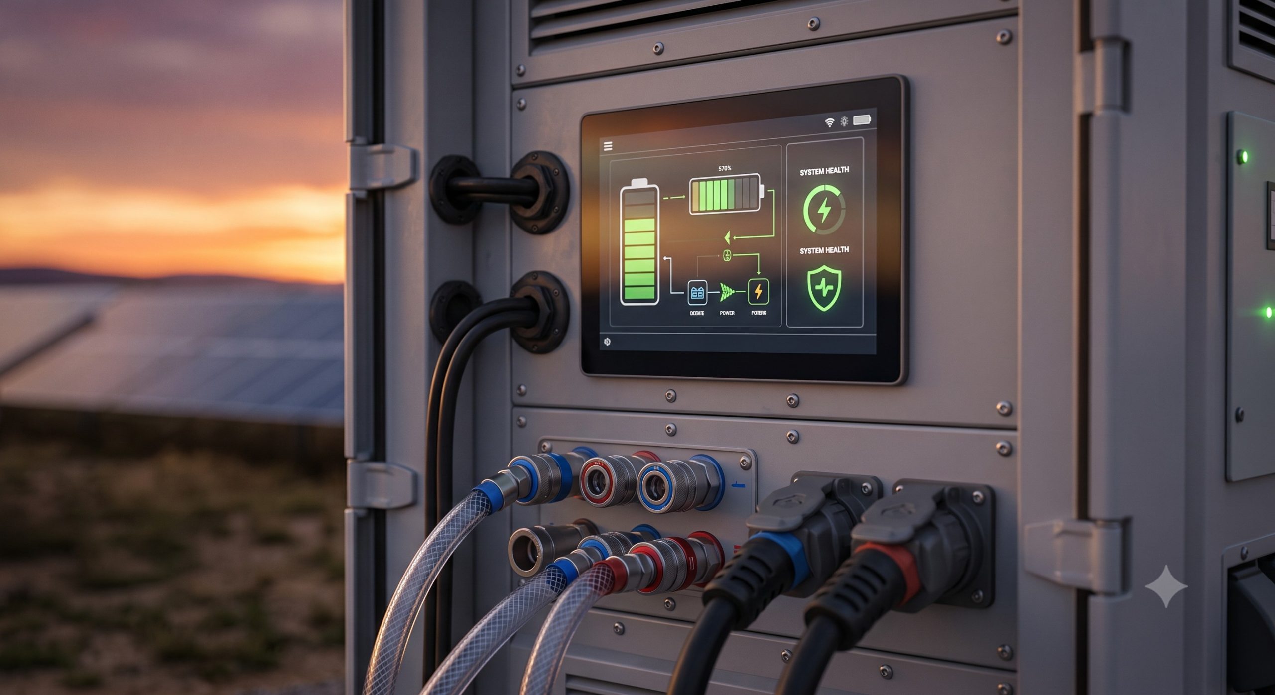
For optimal performance and longevity, the stacked assembly should be deployed in a controlled indoor environment or a purpose-built outdoor rated cabinet (IP55). The ambient operating temperature range is -20°C to +50°C (derating above 45°C). A minimum of 200mm clearance is required on all sides for natural convection air cooling, with increased clearance recommended for liquid-cooled configurations. Proximity to the main electrical service panel should be minimized to reduce AC cable runs and installation costs. The system’s low acoustic noise profile (< 40 dBA) allows for installation in living-adjacent spaces without disturbance, making it a premier choice for residential and small commercial entities seeking to maximize their investment in renewable energy infrastructure.
📥 Download Technical Specification
Click the button below to view or download the full official PDF datasheet.