WALL-MOUNTED RESIDENTIAL BATTERY STORAGE PLATFORM
OFFICIAL PRODUCT OVERVIEW & INSTALLATION REFERENCE GUIDE
DOCUMENT VERSION: 2.1 | RELEASE DATE: 2026-07-06
EXECUTIVE SUMMARY
The global transition towards decentralized, resilient, and sustainable energy infrastructure necessitates a paradigm shift in how residential energy is generated, stored, and consumed. The Wall-mounted Residential Battery (WMRB) platform represents the pinnacle of this evolution, offering a sophisticated, ultra-compact, and aesthetically harmonious energy storage solution designed for seamless integration into modern dwellings. This system is engineered to maximize self-consumption of photovoltaic (PV) energy, provide critical backup power during grid outages, and participate in advanced energy arbitrage and virtual power plant (VPP) programs.
As a Tier-1 global energy storage vendor, we have distilled over a decade of utility-scale and commercial & industrial (C&I) expertise into this residential platform. The WMRB system leverages automotive-grade Lithium Iron Phosphate (LFP) cell technology, a proprietary 5-layer active safety management system, and an intelligent hybrid inverter interface to deliver best-in-class performance, longevity, and safety. This document serves as the definitive technical overview and datasheet, providing system architects, installers, and end-users with a comprehensive understanding of the platform’s architecture, capabilities, and compliance standards.
SYSTEM ARCHITECTURE & INTEGRATION PROTOCOLS
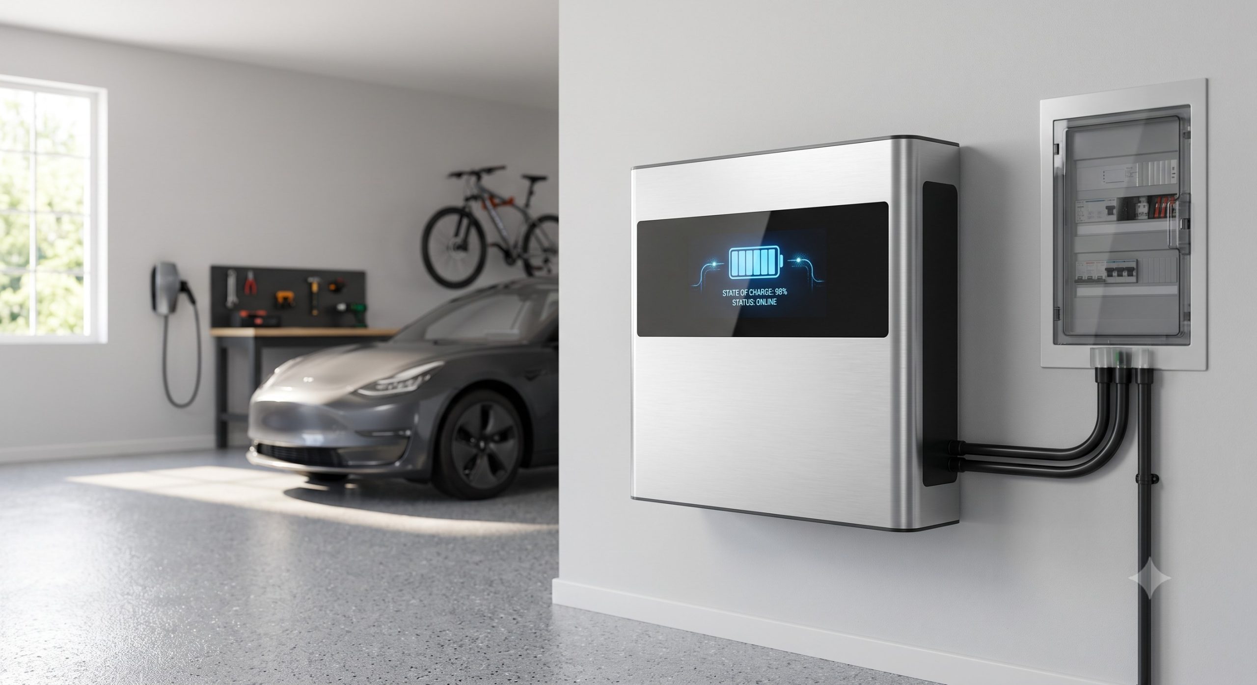
The architecture of the WMRB platform is predicated on a modular, high-voltage DC bus design. The core system components include the Battery Management System (BMS), the Power Conversion System (PCS) interface, and the Energy Management System (EMS) gateway. The following outlines the critical integration protocols and interface standards:
1. HIGH-VOLTAGE DC BUSBAR: The internal architecture utilizes a high-voltage DC busbar (ranging from 150Vdc to 600Vdc). This design enables higher system efficiency, lower current loads on cabling, and facilitates rapid parallel expansion for increased capacity.
2. COMMUNICATION PROTOCOLS: The system supports a wide array of industry-standard communication protocols to ensure interoperability with various third-party inverters, PV string optimizers, and smart home systems. Supported protocols include:
– CAN bus 2.0B (J1939): Primary interface for real-time battery status and control.
– RS485 (Modbus RTU): Standard communication for data acquisition and parameter configuration.
– Wi-Fi / Ethernet (Modbus TCP/IP): For cloud-based monitoring, firmware updates, and VPP dispatch signals.
3. HYBRID INVERTER INTERFACE: The WMRB is optimized for seamless coupling with leading hybrid inverters (compatibility list available upon request). The AC coupling or DC coupling architecture ensures that the battery can charge from and discharge to the grid or PV system with < 100ms response time for backup power transitions. 4. THERMAL MANAGEMENT SYSTEM (TMS): An advanced, passive liquid cooling loop is integrated into the battery modules to maintain optimal cell operating temperatures between 15°C and 35°C. This precise thermal regulation is critical for ensuring a > 6,000 cycle life at 80% depth of discharge (DoD) and is a cornerstone of the platform’s performance ledger.
KEY FEATURES & OPERATIONAL ADVANTAGES
– FEATURE 1: AUTOMOTIVE-GRADE LFP CELL CHEMISTRY: Utilizing prismatic LFP cells sourced from Tier-1 manufacturers. This chemistry inherently provides superior thermal stability, eliminating the risk of thermal runaway under normal operating conditions. The cells are rigorously tested for calendar life ( > 15 years) and provide an industry-leading energy density of > 160 Wh/kg at the module level.
– FEATURE 2: MODULAR PARALLEL EXPANSION CAPABILITY: Designed for future energy needs. The base system configuration supports a single cabinet (e.g., 5 kWh to 15 kWh). However, the architecture allows for the parallel connection of up to 4 cabinets, scaling the total capacity from 5 kWh to a maximum of 60 kWh per single-family dwelling, with no single point of failure across the energy storage system.
– FEATURE 3: INTELLIGENT ENERGY MANAGEMENT SYSTEM (EMS): The proprietary EMS employs a machine-learning algorithm to analyze consumption patterns, local weather forecasts, and real-time time-of-use (TOU) tariffs. This ensures optimal energy arbitrage, maximizing cost savings by charging during low-tariff periods and discharging during peak demand periods.
– FEATURE 4: PREMIUM OUTDOOR & INDOOR RATED ENCLOSURE: The chassis is constructed from heavy-duty, zinc-plated steel with a powder-coated finish (IP65 / NEMA 4X rating). The IP rating guarantees protection against dust ingress and low-pressure water jets, making the unit suitable for both interior garage installations and exterior wall-mount applications. The cabinet is also UV-stabilized and salt-mist resistant (ISO 9227) for coastal environments.
– FEATURE 5: SEAMLESS GRID-TIED & ISLANDING CAPABILITIES: The integration with the hybrid inverter enables the WMRB to operate in both grid-tied and standalone off-grid (islanding) modes. Automatic Transfer Switch (ATS) functionality (provided by the PCS) ensures < 20ms transition from grid failure to backup power, protecting critical household loads.
SAFETY & REGULATORY COMPLIANCE MATRIX
The WMRB platform has been developed to meet or exceed the most stringent international safety and performance standards. The multi-layered safety system includes overcurrent protection, ground fault monitoring, and cell voltage/temperature anomaly detection. Full compliance has been certified by independent third-party testing labs including TÜV Rheinland, UL, and CSA.
CORE CERTIFICATIONS:
- Electrical Safety: IEC 62619 (Safety requirements for secondary lithium cells and batteries), UL 1973 (Standard for Batteries for Use in Light Electric Rail and Stationary Applications).
- Fire Safety: UL 9540 (Energy Storage Systems and Equipment), UL 9540A (Test Method for Evaluating Thermal Runaway Fire Propagation in Battery Energy Storage Systems). The system has successfully passed UL 9540A testing at both the cell, module, and system level.
- EMC/EMI: EN 61000-6-1, EN 61000-6-3, FCC Part 15 Class B.
- Transport: UN 38.3 (Transport of Dangerous Goods).
- Grid Code Compliance: VDE-AR-E 2510-50, CEI 0-21, IEEE 1547.
TECHNICAL SPECIFICATIONS
ELECTRICAL PARAMETERS
- Nominal Voltage: 307.2 Vdc (configurable based on cell count)
- Operating Voltage Range: 240 Vdc to 384 Vdc
- Usable Energy Capacity: 5.12 kWh / 10.24 kWh / 15.36 kWh (Single Cabinet)
- Maximum Scalable Capacity: Up to 60.0 kWh (4 Cabinets in parallel)
- Round-Trip Efficiency (DC): > 95.5% (measured at 0.5C charge/discharge rate)
– Maximum Charge/Discharge Current: 25 A / 25 A (Continuous)
– Peak Discharge Current (1 min): 40 A
– Depth of Discharge (DoD) Recommended: 90% (for optimum cycle life)
| Parameter | Specification | ||||||||||||||||||||||||
|---|---|---|---|---|---|---|---|---|---|---|---|---|---|---|---|---|---|---|---|---|---|---|---|---|---|
| Nominal Capacity (Single Cabinet) | 5.12 kWh / 10.24 kWh / 15.36 kWh | ||||||||||||||||||||||||
| Cooling Method | Passive Convection + Active Liquid Cooling (Dielectric Fluid) | ||||||||||||||||||||||||
| Cell Chemistry | Tier-1 Automotive-Grade LFP (Lithium Iron Phosphate) | ||||||||||||||||||||||||
| Nominal Voltage | 307.2 Vdc | ||||||||||||||||||||||||
| R | o | u | n | d | – | T | r | i | p | E | f | f | i | c | i | e | n | c | y | ( | D | C | ) | ||
| > | 9 | 5 | . | 5 | % | a | t | 0 | . | 5 | C | ||||||||||||||
| Ingress Protection (IP) Rating | IP65 (Indoor & Outdoor Rated) | ||||||||||||||||||||||||
| Communication Protocols | CAN 2.0B, RS485 (Modbus RTU), Wi-Fi/Ethernet (Modbus TCP/IP) | ||||||||||||||||||||||||
| Warranty | 10 Years / 6,000 Cycles (70% Capacity Retention) |
MECHANICAL & ENVIRONMENTAL
– Dimensions (Single Cabinet): Width 450 mm x Height 720 mm x Depth 170 mm (17.7 x 28.3 x 6.7 inches)
– Weight (Single Cabinet): 48 kg (105.8 lbs) for 5.12 kWh variant, 58 kg for 10.24 kWh variant
– Mounting Interface: Wall-mount bracket system (VESA 400×400 compatible base)
– Wall Clearance Requirements: Top 200 mm, Bottom 150 mm, Sides 100 mm, Front 500 mm (for heat dissipation and access)
– Ingress Protection: IP65 (Indoor & Outdoor rated)
– Operating Temperature Range: -20°C to +55°C (with derating above 45°C)
– Storage Temperature Range: -40°C to +60°C (with relative humidity < 90%)
- Altitude: Up to 3000 m above sea level (without performance derating)
- Cooling Method: Passive Convection + Intelligent Active Liquid Cooling (coolant interface type: non-conductive, dielectric fluid)
- Noise Level: < 30 dB(A) at 1 meter (Silent operation)
BATTERY MANAGEMENT SYSTEM (BMS) SPECIFICATIONS
- Cell Balancing: Passive and Active Balancing (Max balancing current: 2 A)
- Monitoring Points: 1 x current sensor, 16 x voltage sensors, 32 x temperature sensors (NTC)
- SOC Estimation Accuracy: < 3% (within 95% confidence interval)
- SOH Estimation: State of Health (SOH) algorithm based on internal resistance and capacity fade model.
- Protection Mechanisms: Over-charge, Over-discharge, Over-current, Short-circuit, Over/Under-temperature, Ground fault detection (Insulation monitoring > 500 kΩ/V)
INSTALLATION PREREQUISITES & GUIDELINES
A successful wall-mounted installation requires adherence to the following prerequisites to ensure safety, performance, and warranty validity.
1. STRUCTURAL INTEGRITY: The mounting surface must be a solid brick, concrete, or structural stud wall capable of supporting a dynamic load of 80 kg (176 lbs) and a static load of 120 kg (264.5 lbs). The wall must be inspected for cracks or structural weaknesses.
2. ELECTRICAL PREPARATION: A dedicated 10 AWG (6 mm²) copper conductor circuit must be provided from the main distribution board (MDB) to the battery installation location. The circuit must be protected with a UL-listed, two-pole circuit breaker rated at 40 A / 600 Vdc.
3. AMBIENT ENVIRONMENT: Ensure the installation site is free of flammable materials, explosive gases, or excessive condensation. The location should have an ambient temperature range between 0°C and 40°C for optimal performance.
4. GROUNDING: The system chassis must be directly connected to a low-impedance earth ground (resistance < 10 Ω) using a #6 AWG (16 mm²) copper ground wire, complying with local NEC (National Electrical Code) or equivalent international standards.
5. ACCESSIBILITY: Maintain a minimum of 500mm of clear space in front of the cabinet to allow for safe access to the EMS touch panel and maintenance ports.
6. NETWORK CONNECTION: For cloud monitoring and remote firmware upgrades, a dedicated Ethernet connection (Cat6 or better) or a strong Wi-Fi signal (2.4 GHz / 5 GHz, RSSI > -65 dBm) is required.
INDUSTRIAL DEPLOYMENT & MICRO-GRID INTEGRATION
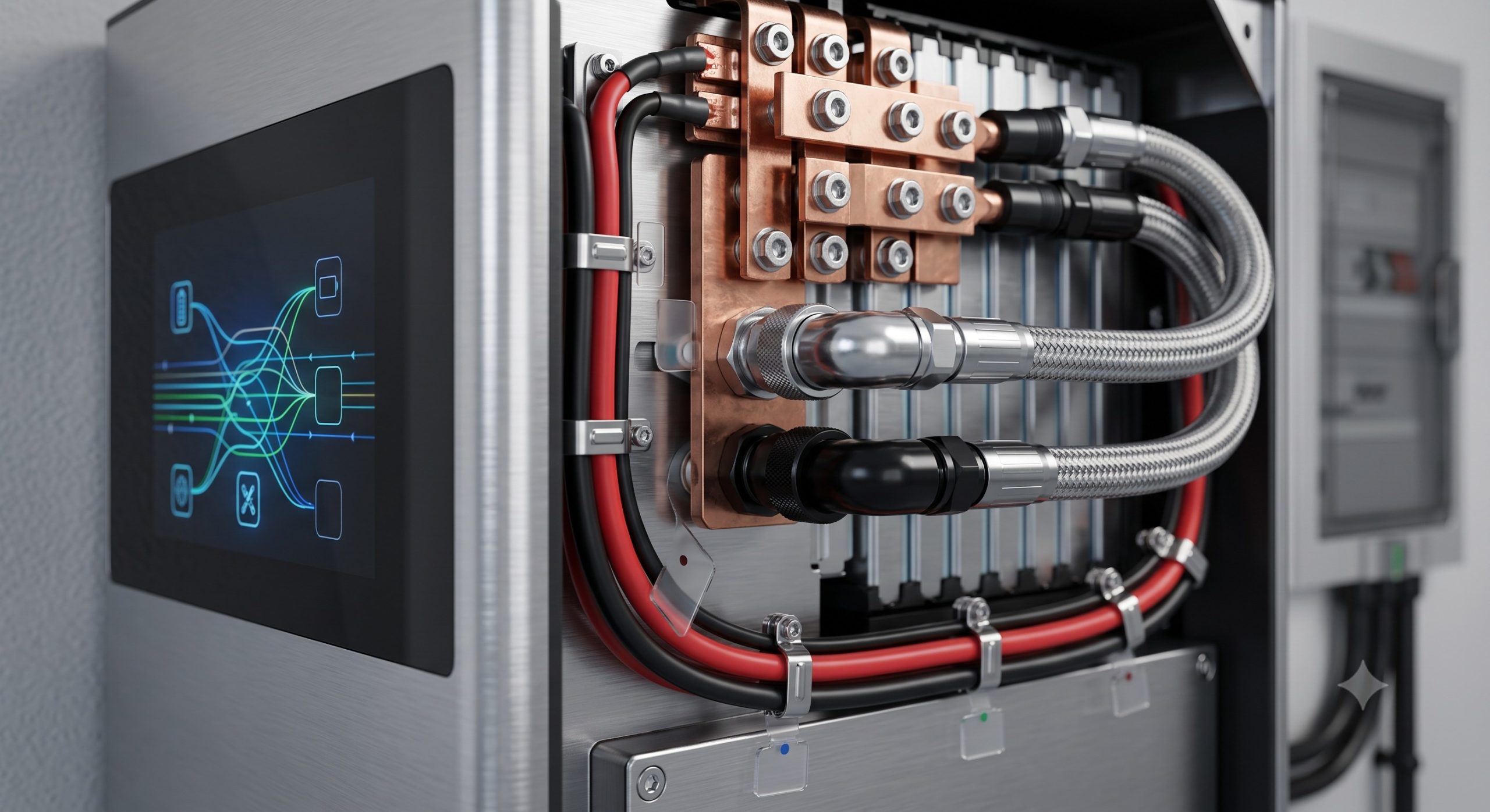
While primarily a residential solution, the WMRB platform’s architecture scales effectively for small commercial applications and local micro-grids. The modular capability allows for the creation of a cohesive energy network where multiple WMRB units (up to 16) can be grouped on a single AC bus. This creates a virtual battery bank managed by a centralized EMS. This configuration is ideal for:
– SMALL OFFICE BUILDINGS: Peak load shaving to reduce demand charges.
– EV CHARGING HUBS: Providing buffer power to support high-power DC fast chargers (up to 50 kW), mitigating grid stress and enabling demand response programs.
– RURAL MICRO-GRIDS: Providing frequency and voltage stabilization in remote or islanded networks, often coupled with existing diesel generators as a hybrid power source.
The platform’s compliance with IEEE 1547 and UL 1741SA ensures smooth and safe interconnection with the utility grid, allowing for import/export of power and participation in ancillary services markets.
WARRANTY & SERVICE AGREEMENT
The WMRB platform is backed by a market-leading 10-year product warranty and a 6,000-cycle performance guarantee at 80% DoD. This ensures that the system will retain at least 70% of its original usable capacity after 10 years or 6,000 cycles, whichever comes first. The comprehensive service package includes:
– 24/7 remote monitoring and diagnostics via our cloud platform.
– Firmware over-the-air (OTA) updates for future functionality and security enhancements.
– Rapid on-site replacement service in case of any hardware failure.
– Extended warranty options available for 15-year coverage.
ABOUT THE MANUFACTURER
As a global leader in energy storage and renewable energy solutions, our company has over 10 GW of energy storage systems deployed globally. Our commitment to innovation, quality, and sustainability has solidified our position as a Tier-1 supplier. We maintain a state-of-the-art manufacturing facility with ISO 9001, ISO 14001, and ISO 45001 certifications, ensuring the highest standards of quality control and environmental responsibility in every product we deliver.
CONTACT US: For technical support, sales inquiries, or to request an official quote, please contact our global team at sales@energy-storage.com or visit our website at www.energy-storage.com.
DISCLAIMER: The specifications provided in this document are subject to change without prior notice to improve performance or reliability. It is the responsibility of the installer to verify local installation codes and regulations. Always refer to the latest official installation manual and safety instructions before commencing installation.
📥 Download Technical Specification
Click the button below to view or download the full official PDF datasheet.