TURNKEY C&I ENERGY STORAGE SOLUTION BRIEF: DEPLOYING COMMERCIAL ENERGY STORAGE INSTALLATION MANUAL
EXECUTIVE SUMMARY
This document serves as the definitive Product Overview and Engineering Reference for the deployment of our Tier-1 Commercial & Industrial (C&I) Energy Storage System (ESS). Designed as a turnkey solution, this platform bridges the gap between renewable generation and grid stability, offering a robust, scalable, and safe architecture for peak shaving, demand response, and backup power applications. This manual consolidates the technical specifications, safety protocols, and installation prerequisites necessary for successful project execution.
SYSTEM ARCHITECTURE & SAFETY
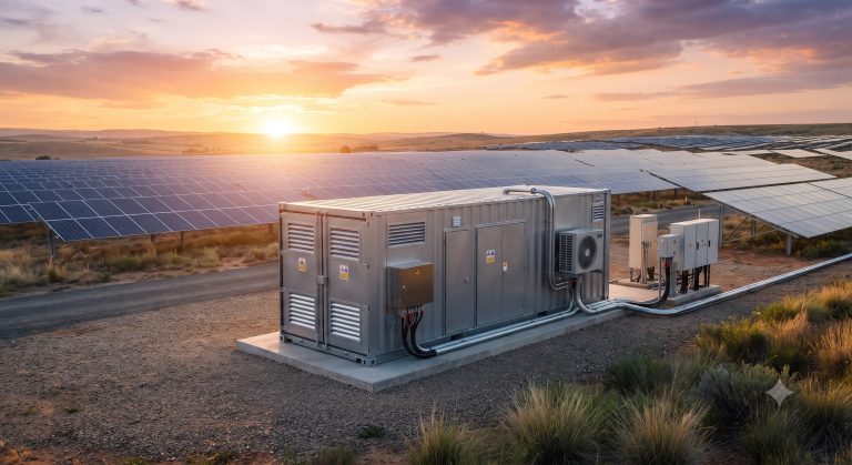
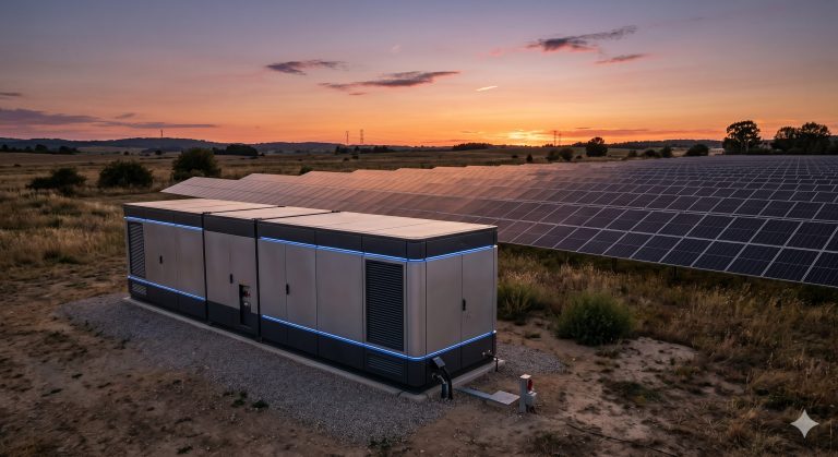
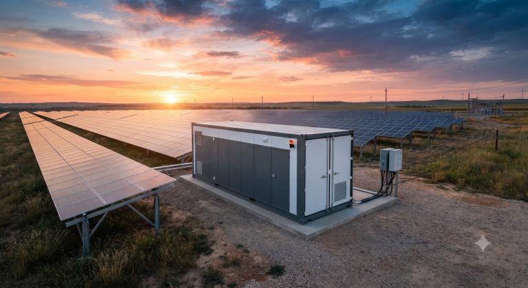
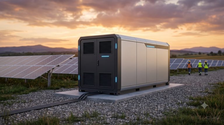
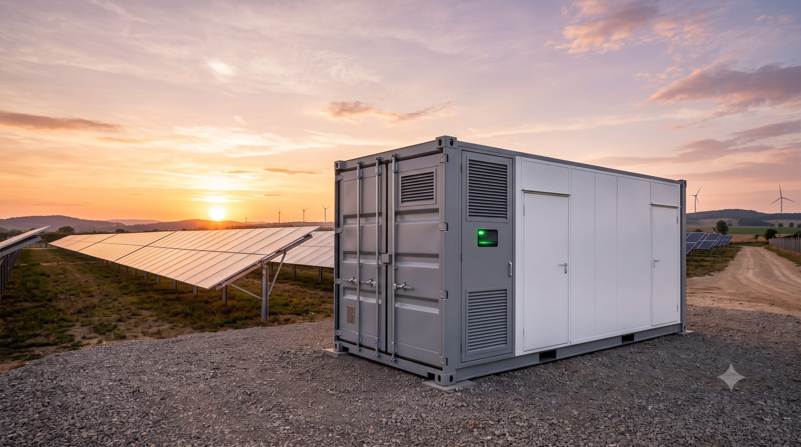
The system integrates high-density Tier-1 LFP battery modules with a bi-directional Power Conversion System (PCS) and an advanced Battery Management System (BMS) within a compact, outdoor-rated enclosure. The architecture is built around a high-voltage DC busbar, optimizing energy transfer efficiency while minimizing internal losses. Safety is paramount, featuring multi-layered protection against overcurrent, short circuits, and thermal events. The system adheres to rigorous global standards, ensuring reliable operation in diverse climatic conditions.
KEY FEATURES
– Modular High-Density LFP Cells: Utilizes prismatic Tier-1 LFP cells, offering superior cycle life and thermal stability with zero cobalt content for ethical and sustainable energy storage.
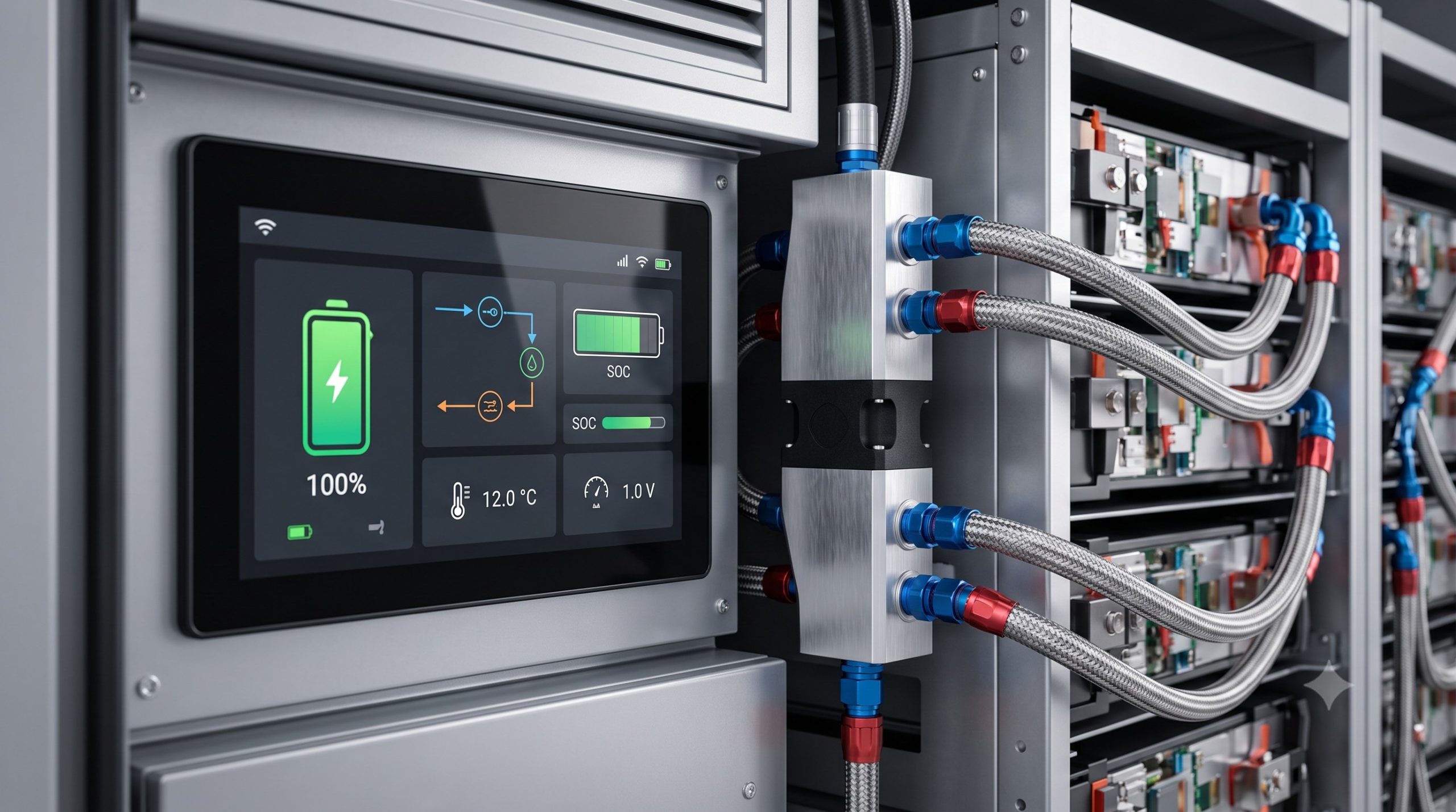
– Smart Liquid Cooling Technology: An intelligent, closed-loop liquid cooling system maintains optimal cell temperature (25°C ± 2°C), significantly enhancing cycle life and ensuring consistent performance even in extreme ambient temperatures.
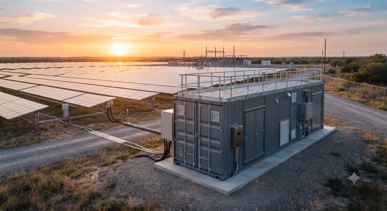
– All-Weather Outdoor Enclosure: IP54-rated cabinet constructed from heavy-duty steel with C5 corrosion resistance, engineered for direct pad installation without the need for additional protective shelters.
– Active Cell Balancing: A proprietary BMS employs real-time active balancing across all cells, maximizing usable capacity and extending the system’s operational lifespan by over 15% compared to passive systems.
– Seamless Grid Interface: The bi-directional PCS supports seamless on-grid and off-grid transition (islanding), enabling uninterrupted power supply (UPS) functionality for critical loads.
COMPLIANCE & STANDARDS
The system is fully certified according to leading international safety and performance regulations, mitigating project risks and simplifying local permitting processes.
– Safety: UL 9540, UL 1973, IEC 62619, IEC 62477
– EMC: FCC Part 15, IEC 61000-6-2, IEC 61000-6-4
– Grid Interconnection: IEEE 1547, UL 1741 (with SA), VDE-AR-E 2510-50
– Transportation: UN 38.3 for lithium batteries
TECHNICAL SPECIFICATIONS
GENERAL PARAMETERS
– System Energy Capacity: 215 kWh / 372 kWh per base cabinet (expandable)
– System Power (AC): 100 kW / 150 kW nominal
– AC Output Voltage: 380/400/415 VAC (3W + N + PE), 50/60 Hz
– Battery Chemistry: Lithium Iron Phosphate (LFP), Prismatic Cells
– Rated Voltage Range (DC): 600 V – 850 V
– Round-trip Efficiency: > 90% (DC/AC)
– Cooling: Smart Liquid Cooling with integrated chiller
– Protection Rating: IP54 (Cabinet), IP67 (Battery Submodules)
PERFORMANCE & OPERATIONAL DATA
– Operating Temperature Range: -30°C to +55°C (with derating)
– Relative Humidity: 0 – 95% (non-condensing)
– Max. Altitude: 3000 m (derating above 2000 m)
– Cycling Capability: > 8,000 cycles at 25°C (80% DoD, EOL 80%)
– Communication Protocols: Modbus RTU/TCP, CAN, DNP3, IEC 61850 (optional)
– Dimensions (W x D x H): 1800 mm x 1200 mm x 2200 mm (per cabinet)
– Weight: Approx. 2,900 kg (fully populated)
| Parameter | Specification (Base Cabinet) |
|---|---|
| Nominal Capacity (AC) | 100 kW / 215 kWh |
| Cooling Method | Smart Liquid Cooling (Chiller-integrated) |
| Cell Chemistry | Tier-1 LFP (Prismatic) |
| Voltage Range | 600 – 850 VDC |
| Cycle Life | 8,000 cycles at 25°C (80% DoD, EOL 80%) |
| Enclosure Protection | IP54 (Cabinet) / IP67 (Battery Modules) |
| Operating Temperature | -30°C to +55°C |
INDUSTRIAL DEPLOYMENT & INSTALLATION GUIDELINES
Successful deployment begins with meticulous site preparation. The installation manual details critical steps to ensure system integrity and long-term performance.
– Pad Preparation: The system requires a level, reinforced concrete pad with a minimum compressive strength of 28 MPa. The pad must include integrated grounding points and cable trenches for power and communication lines.
– Lifting & Positioning: A dedicated lifting plan using certified spreader bars is provided to safely hoist and position the cabinet without stressing structural points.
– Cooling System Commissioning: The liquid cooling circuit must be filled with the specified coolant (water/ethylene glycol mix) and purged of air. Initial startup procedures include verifying flow rates and leak checks.
– Electrical Interconnection: Detailed wiring diagrams guide the connection of AC mains, auxiliary supply, and the DC busbar for parallel expansion. All terminations must be torqued to specified values to prevent hot spots.
– EMS Integration: The system includes a pre-configured Energy Management System (EMS) for intuitive local control and remote monitoring via a secure cloud platform, enabling real-time performance analytics and O&M alerts.
📥 Download Technical Specification
Click the button below to view or download the full official PDF datasheet.