Overview
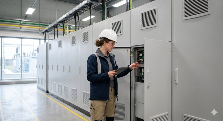
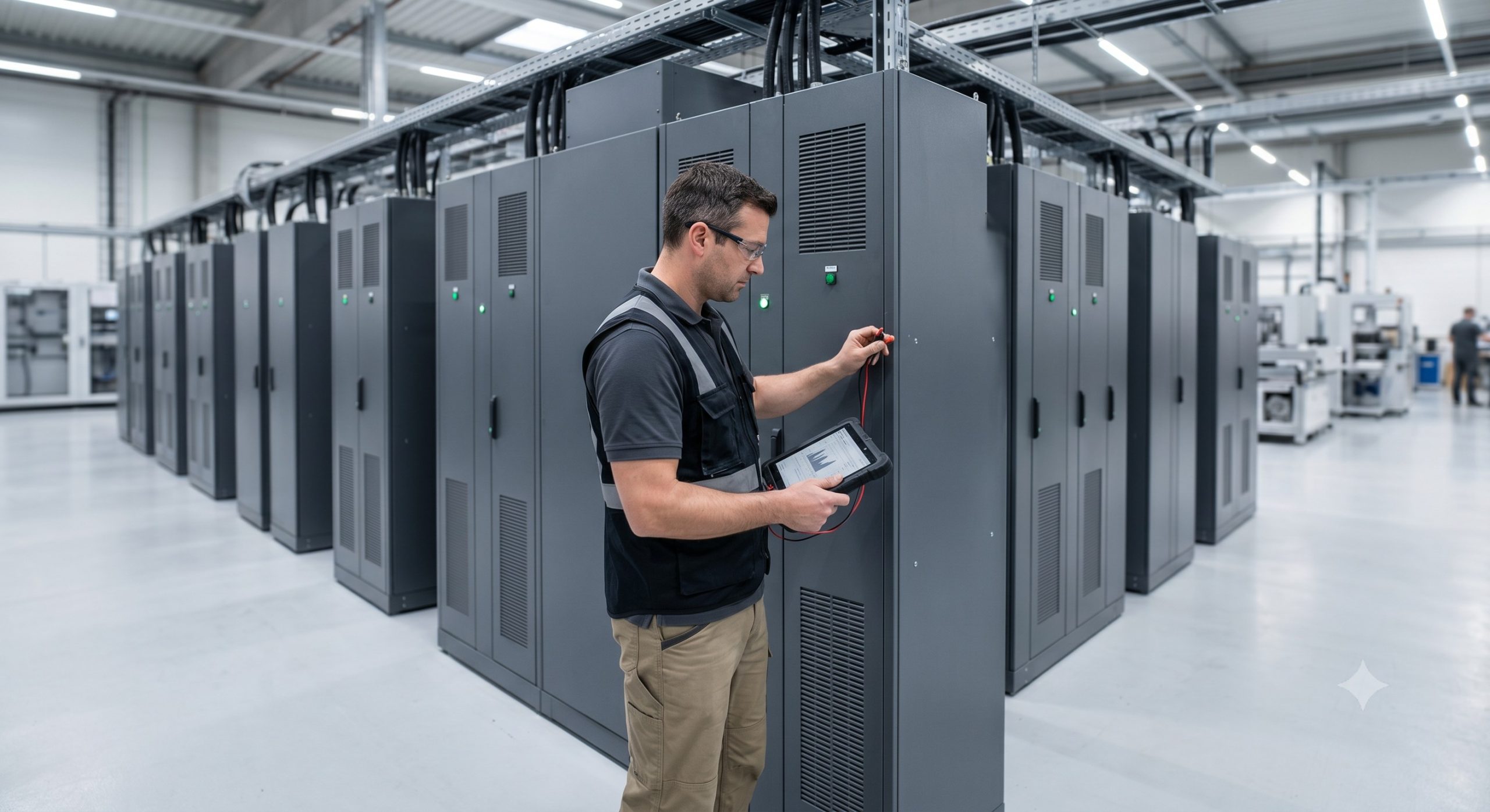
Deploying a 1MW C&I storage system requires careful planning across space, safety, and performance. This FAQ addresses the most critical pre-sales and post-sales technical questions from plant engineers and procurement teams, providing definitive answers for a successful BESS installation and operation.
Frequently Asked Questions
- Q1: What are the exact installation space requirements for a 1MW C&I storage system?
- Standard 1MW/2MWh C&I storage systems typically require a 40-foot ISO container footprint of approximately 12m x 2.5m (30 sqm) or equivalent modular cabinet layout. Total service area, including 1m clearance for ventilation and access, is roughly 40-50 sqm. Additional space for PCS, transformer, and grid interconnection (often housed in a separate 20-foot container or external pad) adds roughly 15-20 sqm, bringing the total grade-level footprint to 55-70 sqm.
- Q2: What is the standard cycle life and recommended DoD for a 1MW LFP BESS?
- For a 1MW LFP-based C&I system, standard cycle life is 6,000 cycles at 80% Depth of Discharge (DoD) and 10,000 cycles at 70% DoD. This longevity is achieved through passive or liquid thermal management, keeping cell temperatures between 15-35°C. For economic optimization, we recommend an 80% DoD setting for daily peak shaving, which typically yields a 10-year operational lifespan with less than 20% capacity degradation.
- Q3: How does the liquid cooling system improve performance and safety for a 1MW storage system?
- Liquid cooling is superior to air cooling for 1MW systems as it maintains cell temperature variance within ±2°C, preventing hot spots and extending cell life by up to 15%. The closed-loop coolant circuit efficiently dissipates the 300-400kW of heat generated at full load, ensuring stable operation and enhancing thermal runaway prevention by keeping cells below critical temperatures. It also enables a more compact, space-efficient layout compared to air-cooled designs.
- Q4: What are the fire safety and thermal runaway prevention mechanisms in a modern 1MW BESS?
- A multi-layer safety system is standard: early gas detection (CO, H2), aerosol or water-mist fire suppression, and inter-module isolation using fire-retardant materials. At the cell level, LFP chemistry provides inherent thermal stability with a decomposition temperature over 500°C. The BMS continuously monitors voltage and temperature, immediately disconnecting the PCS if any cell exceeds safe limits. This combined approach meets stringent UL 9540A requirements for large-scale installations.
- Q5: How does the BMS monitor and balance cells in a 1MW C&I BESS?
- The BMS performs cell-level voltage and temperature monitoring across all 3,000+ cells, utilizing passive balancing to equalize cell state-of-charge. Advanced algorithms, including machine learning, predict cell degradation and adjust balancing thresholds to prevent over-discharge or over-charge of weak cells. This active oversight maximizes usable capacity and ensures safe, reliable operation throughout the system’s 10-15 year design life.
- Q6: Can a 1MW BESS be scaled or paralleled for future capacity expansion?
- Yes, 1MW systems are designed for modular scalability using a shared DC busbar or AC-coupled architecture. You can add identical units in parallel, with the central Energy Management System (EMS) coordinating dispatch and SOC balancing. Each additional 1MW cabinet connects to a custom DC busbar linkage, allowing scalable expansions up to 10MW or more for microgrid or large-scale industrial applications.
- Q7: What configurations are supported: grid-tied, off-grid, or hybrid?
- All three: grid-tie for peak shaving and demand response, off-grid for island mode, and hybrid with automatic transfer switching. The bi-directional PCS supports seamless transition in under 20ms for sensitive industrial loads. In grid-tied mode, it manages power factor correction and harmonics; in off-grid mode, it uses V/f control to establish a stable microgrid, making it suitable for diesel replacement and remote industrial sites.
- Q8: How is the ROI calculated for a 1MW storage system, and what is the payback period?
- ROI is calculated using peak shaving savings, demand charge reduction (typically $10-20/kW), and time-of-use arbitrage revenue. For a standard 1MW/2MWh unit, average annual savings are $100,000-$180,000 depending on local utility rates. Net cost after tax incentives is approximately $350,000-$450,000, yielding a payback period of 2-3 years and a 15-30% internal rate of return (IRR) over its 10-year lifespan.