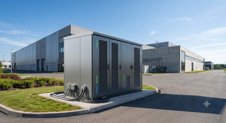
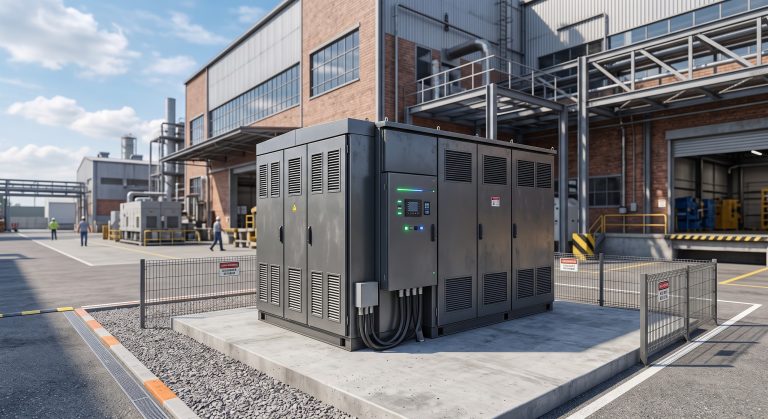
Introduction: The Economic Imperative of Commercial Energy Storage
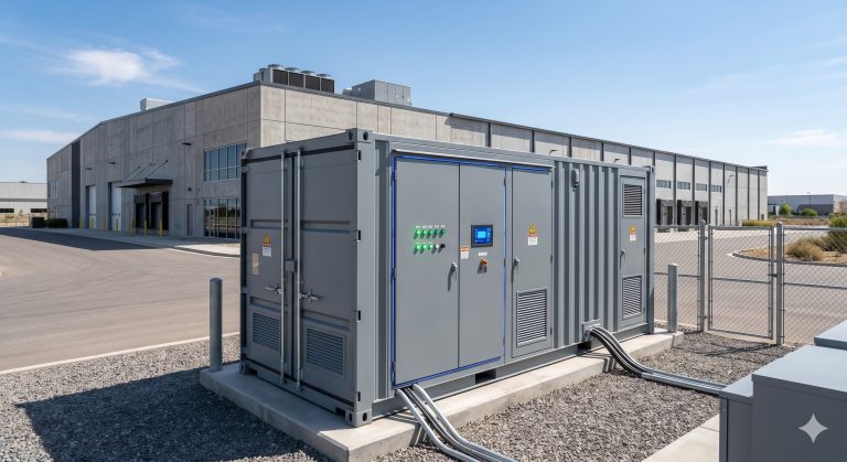
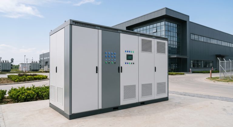
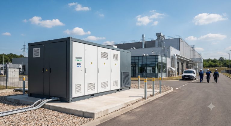
Global commercial electricity tariffs have experienced an average annual increase of 5.7% over the past three years, with peak demand charges now accounting for up to 40% of a facility’s total utility bill. This has transformed the C&I energy storage system from a ‘green luxury’ into a critical financial instrument for demand-side management. For enterprise decision-makers, understanding the intricate balance between capital expenditure (CapEx) and operational expenditure (OpEx) is the first step toward achieving energy independence. Unlike traditional uninterruptible power supplies (UPS), modern commercial energy storage systems are engineered for daily cycling and active market participation. A well-architected BESS (Battery Energy Storage System) can achieve a payback period of under four years in high-tariff regions, with a Levelized Cost of Storage (LCOS) dipping below $0.12/kWh, making it not only an environmental statement but a proven hedge against inflation and supply volatility.
Core Architecture & Battery Management Systems
Power Conversion System (PCS) Bi-Directional Flow
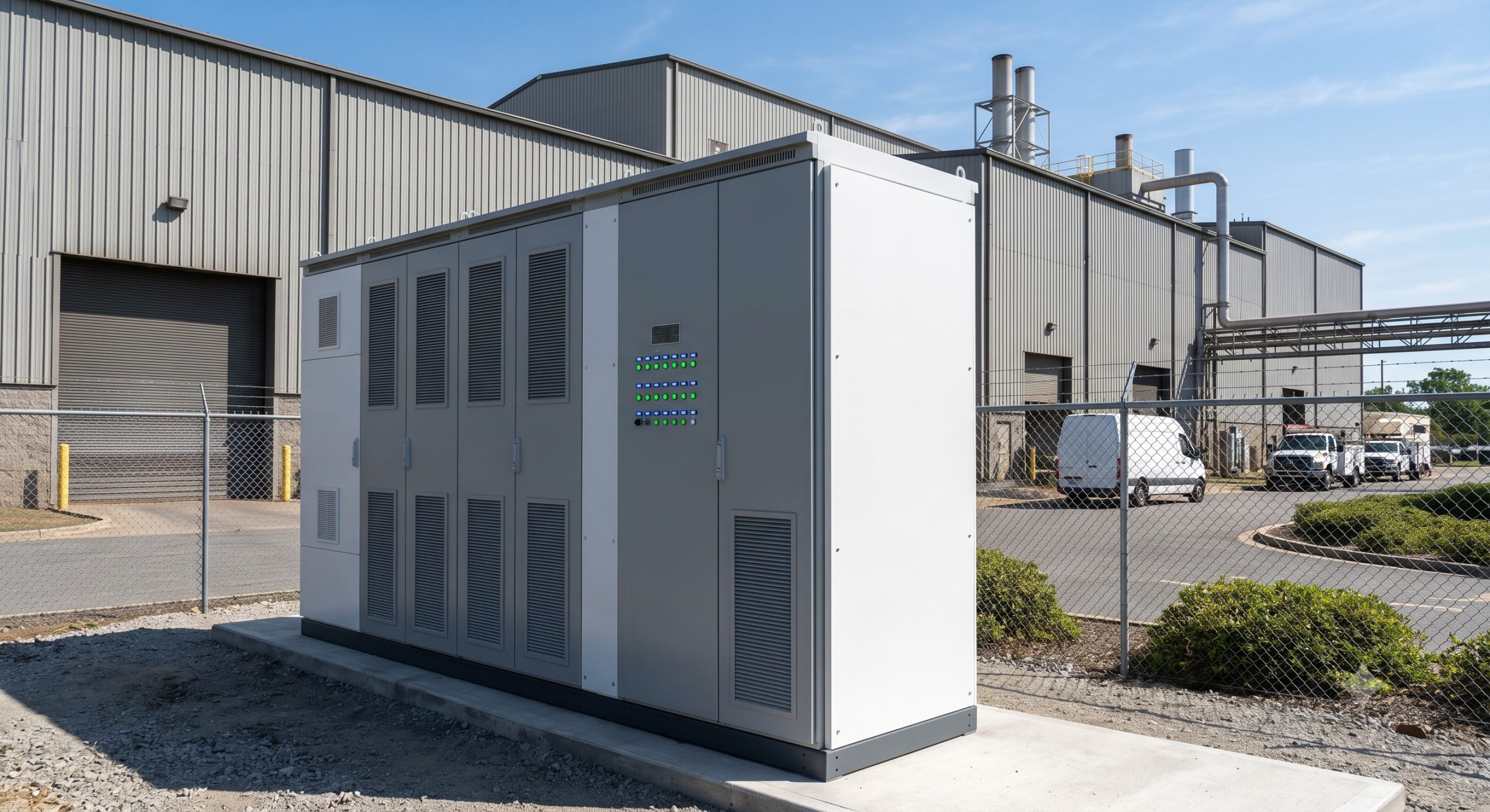
At the heart of any C&I energy storage system lies the Power Conversion System (PCS). The PCS is responsible for the bi-directional conversion between AC and DC power, enabling both grid-to-battery charging and battery-to-facility discharge. Modern system integrators prioritize modular PCS configurations with a minimum efficiency of 98.5% under full load, as even a 0.5% efficiency delta can translate to thousands of dollars in annual energy losses. For high-performance applications, the integration of liquid cooling PCS has become a benchmark standard, allowing the inverter to maintain peak output even at ambient temperatures of 45°C without derating.
Battery Management System (BMS) & Tier-1 LFP Cells
Procurement managers must differentiate between generic pack assemblers and Tier-1 cell manufacturers. A robust BMS architecture utilizes a three-tiered topology: Cell Monitoring Units (CMU), Board Management Units (BMU), and a Cluster Management Unit (CMU) that communicates directly with the Energy Management System (EMS). The gold standard for current C&I projects is the use of Tier-1 LFP (Lithium Iron Phosphate) battery cells with capacities ranging from 280Ah to 314Ah. LFP chemistry is preferred for its thermal stability and extended calendar life. Crucially, a premium BMS offers passive and active cell balancing, ensuring that voltage deviations are kept below ±20mV across thousands of cells, which is a non-negotiable requirement for maintaining capacity integrity over a 10-year project lifespan.
Thermal Management: Liquid Cooling vs. Air Cooling ESS
Thermal regulation is the single most critical factor in determining the actual cycle life of a C&I energy storage system. While air-cooled systems remain cost-effective for smaller 30kW/60kWh cabinet configurations, high-density 1MWh+ containers now mandate liquid cooling ESS technology. Liquid cooling offers a heat exchange efficiency that is 2-3x greater than air, maintaining cell temperature differences (ΔT) within a stringent 2-3°C range, versus 5-8°C for air-cooled alternatives. This precision prevents the formation of hotspots that accelerate solid electrolyte interface (SEI) growth and lithium plating, directly preserving the integrity of the Battery Energy Storage System. For large-scale industrial parks, a liquid cooling thermal control system is the prerequisite for maintaining a cycle life of >8000 cycles at a 90% Depth of Discharge (DoD).
Technical Specifications & Performance Metrics
Engineering specifications require objective, verifiable data. The procurement team should focus on the specification ledger that defines the true operational boundaries of the commercial energy storage asset. The following table distills the core performance metrics that distinguish high-grade Tier-1 equipment from substandard alternatives, essential for any comprehensive BESS wholesale evaluation.
| Key Parameter | Technical Specification |
|---|---|
| Battery Chemistry | Tier-1 LFP (Lithium Iron Phosphate) |
| Rated Capacity | Customizable (e.g., 1MWh – 5MWh per unit) |
| Cycle Life | >8000 cycles @ 90% DoD |
| Round-Trip Efficiency | ≥92% (DC/AC, including auxiliary consumption) |
| Thermal Management | Advanced Liquid Cooling (ΔT < 3°C) |
| Safety Certification | IEC 62619, UL 9540, CE, UN38.3 |
| Response Time | <100ms for full power conversion |
| BMS Voltage Precision | ±20mV active cell balancing |
Commercial ROI: Total Cost of Ownership and Peak-Shaving
The financial case for a C&I energy storage system hinges on two primary value streams: energy arbitrage and demand charge management. In markets like the US and Germany, peak demand charges can exceed $20/kW, representing 30-50% of the utility bill. By deploying a commercial energy storage solution with a rapid response time of <100ms, facilities can effectively 'peak shave', reducing demand spikes by up to 40%. Furthermore, for facilities integrating onsite solar PV, the system enhances self-consumption ratios from 40% to over 90%, curtailing the need to sell solar energy back to the grid at wholesale rates. The Total Cost of Ownership (TCO) must account for degradation. However, by maintaining a conservative 90% DoD and utilizing advanced active balancing, the Battery Energy Storage System maintains a capacity retention of 80% at the 10-year mark, ensuring reliable amortization of the initial CapEx.
Deployment Scenarios & Grid Support
PV-Storage-Charging Synergy
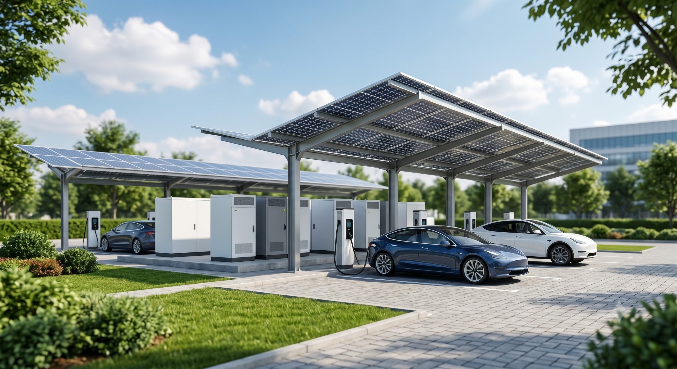
One of the most lucrative deployment architectures is the integration of PV-Storage-Charging for EV supercharging stations. A C&I energy storage system acts as a ‘power buffer’ for EV chargers, alleviating the need for costly grid upgrades. The system stores solar energy during peak sunlight hours (10:00 AM to 2:00 PM) and discharges it to vehicles during evening peaks, realizing maximum revenue capture. This synergy effectively transforms a charging station into an autonomous micro-grid with minimal grid dependency.
Industrial Parks and Micro-Grids
Large industrial parks, particularly those in the chemical and manufacturing sectors, benefit from the Modular Scaling Topology of the BESS. Parallel cabinet expansion allows for incremental scaling from a starting capacity of 500kWh to multi-MWh deployments. By integrating a Smart EMS capable of Demand Response (DR) signaling, these systems provide frequency regulation and voltage support to the utility grid, turning the facility into a Virtual Power Plant (VPP). This not only provides a secondary revenue stream through grid service incentives but also fortifies the facility against brownouts and grid instability.
Conclusion: The Zero-Carbon Migration Roadmap
The migration toward a decentralized, decarbonized energy grid is contingent on the scalable deployment of advanced C&I energy storage systems. As global regulatory frameworks tighten around carbon emissions, integrating a Battery Energy Storage System is no longer an optional upgrade but a strategic imperative for maintaining competitive advantage. The evidence-based results from early adopters demonstrate that the technology transcends basic backup power, driving a new paradigm of operational efficiency and grid resilience. For enterprise leaders, the time to act is now, leveraging the robust architecture, superior LCOS, and compliance certifications like UL 9540 and IEC 62619 to secure a reliable, profitable, and sustainable energy future. By implementing these advanced systems, C&I facilities are not just consuming power; they are actively participating in the architecture of the smart grid.