PV-STORAGE-CHARGING INFRASTRUCTURE REFERENCE DESIGN GUIDE FOR EV CHARGING PLUG
EXECUTIVE SUMMARY
The rapid global proliferation of electric vehicles (EVs) demands a corresponding evolution in charging infrastructure, moving beyond simple grid connections toward intelligent, resilient, and sustainable energy ecosystems. The EV Charging Plug, when integrated within a photovoltaic (PV) and energy storage system (ESS) framework, represents the definitive hardware interface for this transition. This document serves as a comprehensive reference design guide for system integrators, facility engineers, and infrastructure developers. It details the technical architecture, performance specifications, safety protocols, and compliance standards for deploying the EV Charging Plug as the central dispatching point within a commercial and industrial (C&I) PV-storage-charging micro-grid. This document outlines the critical role of the charging plug as the primary load interface, ensuring seamless bi-directional energy flow, enhanced grid stability, and optimized economic performance through peak shaving and demand response.
SYSTEM ARCHITECTURE & INTEGRATION LOGIC
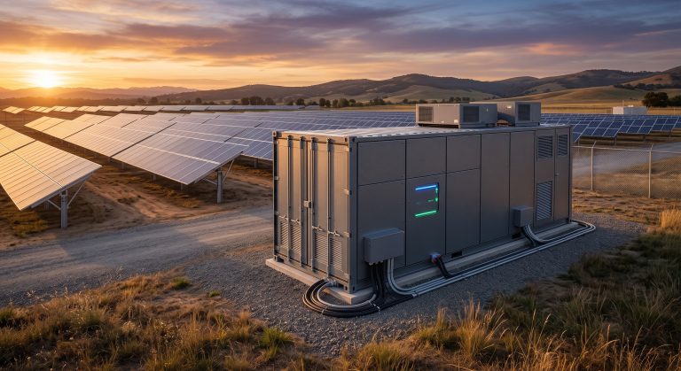
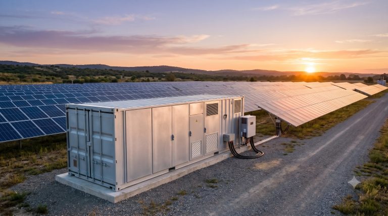
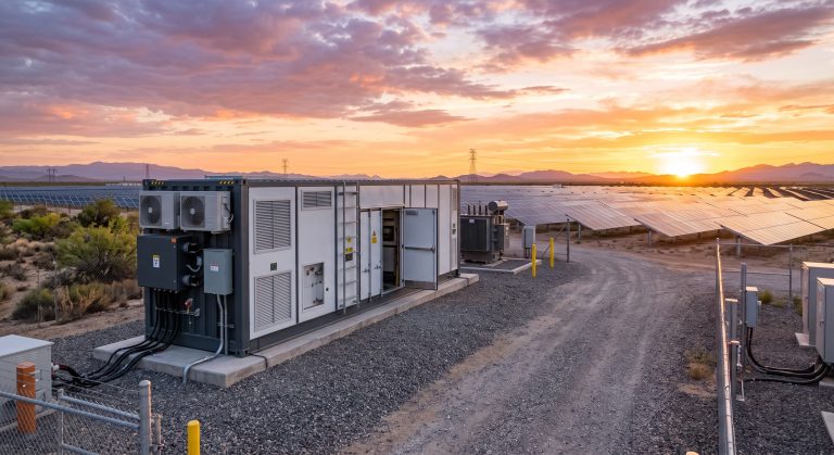
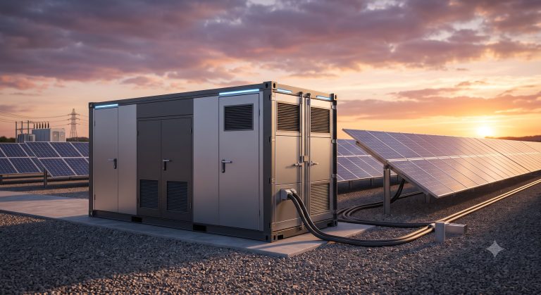
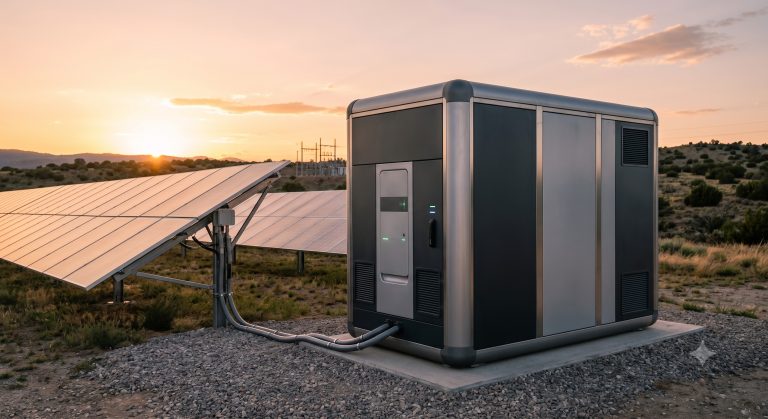
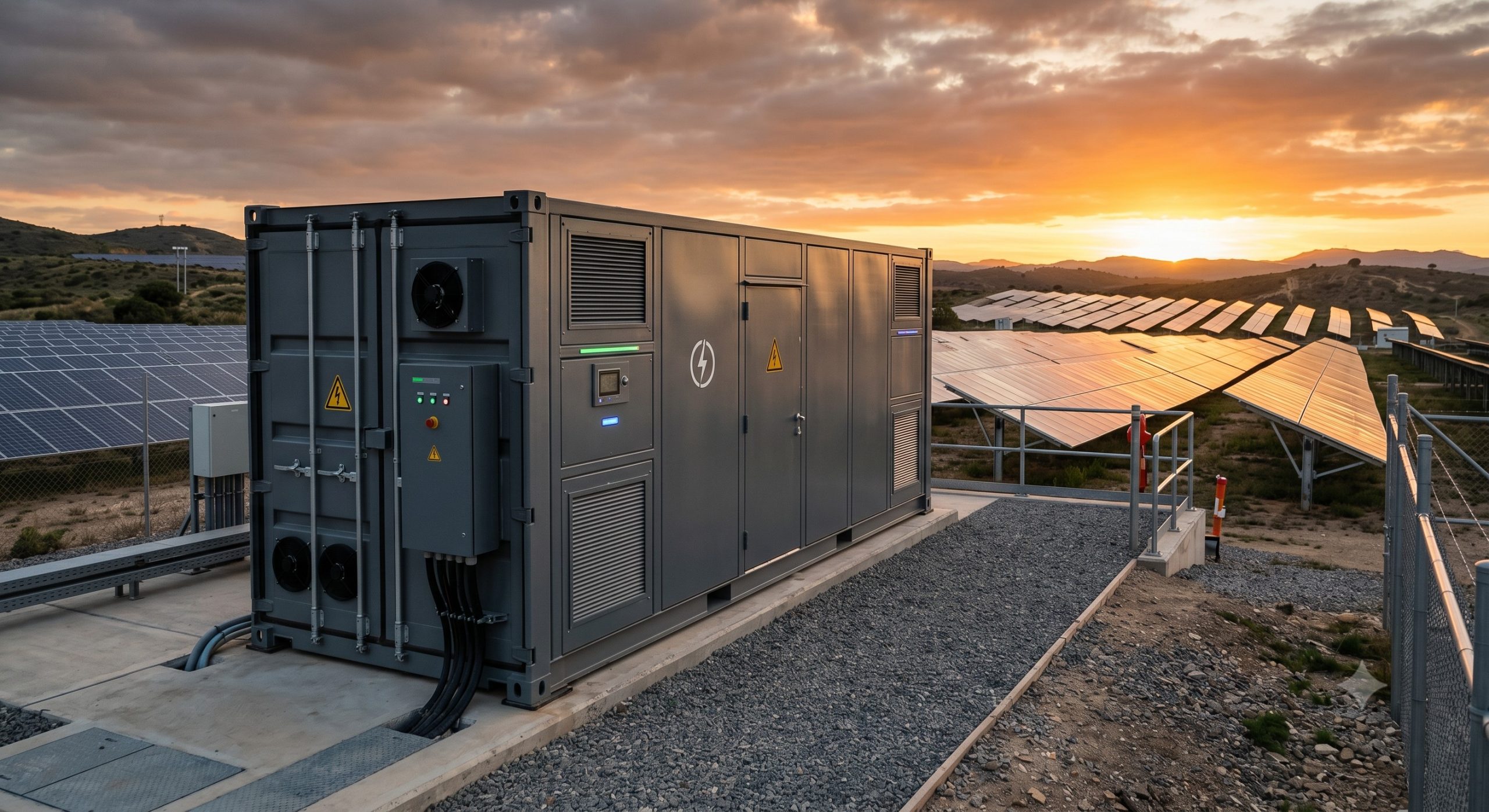
The EV Charging Plug is not an isolated component but a sophisticated terminal within a larger, orchestrated energy network. Its architecture is defined by its integration with three core subsystems: the PV generation array, the battery energy storage system (BESS), and the utility grid interface. The primary communication and power dispatch are managed by the central Energy Management System (EMS), which executes real-time decisions based on load demand, PV availability, state of charge (SoC), and time-of-use (ToU) tariff structures. The charging plug acts as the final actuator in this chain, receiving power from a bi-directional common DC bus or an AC-coupled inverter system. This topology ensures maximum self-consumption of solar energy, reduces peak demand charges, and provides backup power capabilities during grid outages. The hardware is designed for outdoor deployment, featuring robust IP-rated enclosures and intelligent thermal management to ensure consistent performance across diverse climatic conditions.
KEY FEATURES
– Seamless PV-ESS Integration: The EV Charging Plug is designed for direct compatibility with DC and AC-coupled storage systems, allowing for dynamic power sharing. It intelligently prioritizes solar energy for EV charging, storing excess PV generation for later use, and only drawing from the grid as a last resort, thus maximizing the return on investment for solar assets.
– Bi-Directional Power Capability (V2G Ready): The plug interface supports Vehicle-to-Grid (V2G) protocols, enabling future compatibility with bi-directional EV chargers. This transforms EVs from simple loads into distributed energy resources (DERs), capable of feeding stored energy back to the facility or grid during peak price periods, creating a new revenue stream and enhancing energy resilience.
– Smart Dispatch & Demand Response: Integrated with the EMS, the charging plug is capable of modulating its power output in response to grid operator signals. It can curtail charging during peak load events or participate in frequency regulation markets, providing a valuable grid service while lowering operational costs for the facility owner.
– Enhanced Safety & Protection: The unit incorporates a multi-layered safety architecture, including overcurrent protection, ground fault monitoring (GFCI), surge protection, and arc-fault detection. It is engineered with a reinforced chassis and thermal shutdown mechanisms to protect against environmental hazards and electrical faults, ensuring personnel and asset safety.
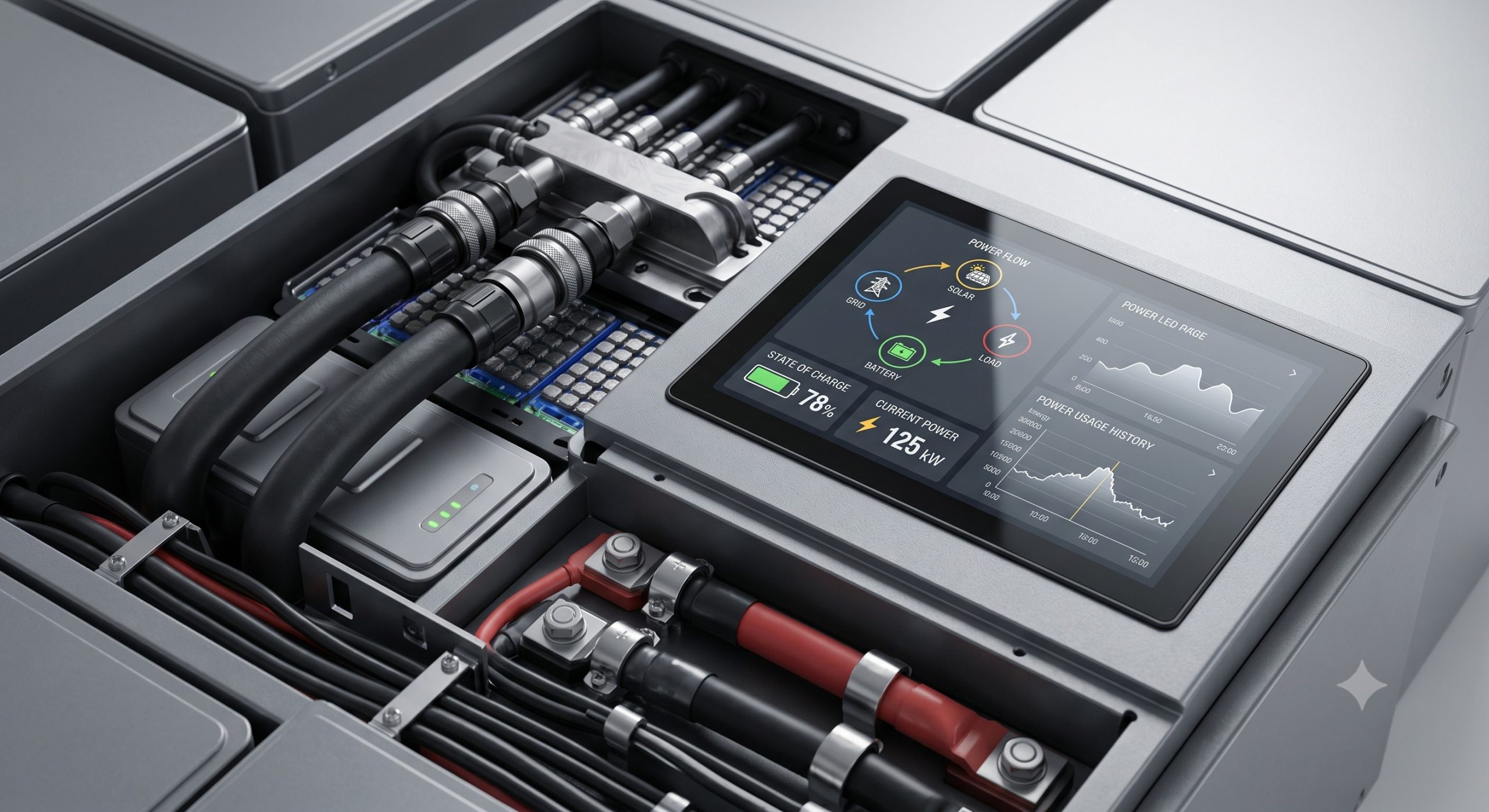
– Advanced Metering & Auditability: Equipped with high-precision, revenue-grade metering (AC & DC) with bi-directional capability, the EV Charging Plug enables precise energy accounting. This data is essential for load management, tenant sub-billing, and verifying the performance of the entire micro-grid infrastructure, providing full transparency and operational control.
COMPLIANCE & STANDARDS
Adherence to global and regional standards is non-negotiable for ensuring safety, interoperability, and long-term project viability. The EV Charging Plug is designed to meet and exceed a comprehensive suite of international standards.
– Electrical Safety: The device is engineered in full compliance with IEC 61851-1 (General requirements for EV conductive charging systems) and IEC 61851-23 (DC EV charging station). This covers all aspects of electrical safety, protection against electric shock, and environmental durability.
– Communication & Interoperability: Standards compliance includes ISO 15118 for V2G communication, ensuring seamless and secure handshake protocols with a wide variety of EV models. This enables plug-and-charge capabilities and smart energy management functionalities.
– Global Certifications: The hardware is prepared for region-specific certifications, including UL 2594 (Standard for Electric Vehicle Supply Equipment) for the North American market, and CE marking for the European market, ensuring a streamlined path to regulatory approval in major economic regions.
– EMC & Environmental: The charging plug adheres to strict Electromagnetic Compatibility (EMC) standards (e.g., IEC 61000 series) to prevent interference with other sensitive equipment. It also meets ingress protection (IP) and impact resistance (IK) standards suitable for outdoor, public-facing installations.
TECHNICAL SPECIFICATIONS
The following section details the core electrical and physical parameters of the EV Charging Plug. For comprehensive project-specific configurations, please refer to the detailed engineering schematics provided in the full system integration manual.
CONNECTOR INTERFACE & RATINGS
– Output Type: Type 2 (IEC 62196-2) / CCS Combo 1 & 2, with options for GB/T for specific regions.
– Nominal Voltage (AC Input): 400V ±10% (Three-phase) / 480V ±10% (Three-phase).
– Nominal Voltage (DC Output): 200V – 1000V (wide voltage range for universal EV compatibility).
– Maximum Output Current (DC): 200A (continuous) / 350A (boost for specific EV models).
– Rated Power Output: Up to 150kW (DC) / 22kW (AC) per plug, with support for modular expansion.
– Frequency: 50/60 Hz.
COMMUNICATION & CONTROL
– Communication Protocol: OCPP 1.6J / 2.0.1 (Open Charge Point Protocol) for seamless backend integration. Other protocols (e.g., Modbus TCP, CAN bus) available for direct EMS integration.
– Connectivity: 4G/LTE, Wi-Fi, and Ethernet (RJ45) for robust network connectivity and remote firmware updates.
– Metering Accuracy: Class 0.5S (bi-directional) for sub-billing and asset performance tracking.
– Emergency Stop: Integrated, hardwired emergency stop button compliant with ISO 13850.
ENCLOSURE & PHYSICAL SPECIFICATIONS
– Ingress Protection: IP54 (indoor/outdoor) / IP65 (front panel).
– Impact Protection: IK10.
– Operating Temperature: -30°C to +55°C (with de-rating above 45°C) / -30°C to +50°C (full power).
– Relative Humidity: 5% to 95% (non-condensing).
– Altitude: Up to 2000m above sea level (derating above).
– Cooling Method: Intelligent forced air cooling with variable speed fans.
– Mounting: Floor-standing (pedestal) or wall-mounted options.
| Parameter | Value / Specification |
|---|---|
| Connector Type | Type 2 / CCS Combo 1 / CCS Combo 2 |
| Rated Output Power (DC) | Up to 150kW (Boost Mode: 350A) |
| Nominal Output Voltage (DC) | 200V – 1000V |
| Communication Protocol | OCPP 1.6J/2.0.1, Modbus TCP |
| Ingress Protection (IP) | IP54 (Enclosure) / IP65 (Front Panel) |
| Operating Temperature Range | -30°C to +55°C (derating above 45°C) |
| Metering Accuracy | Class 0.5S (Bi-directional) |
INDUSTRIAL DEPLOYMENT & SCALING
Successful deployment of the EV Charging Plug within a C&I micro-grid requires a systematic approach to site assessment, power distribution planning, and scalability. The following guidelines ensure optimal performance and future-proofing.
– Site Assessment & Load Profiling: A thorough audit of the facility’s daily load profile, peak demand, and average EV charging requirements is the first critical step. This data, combined with local solar irradiation data, informs the sizing of the PV array and BESS capacity to maximize the utilization of the EV Charging Plug.
– Power Distribution & Grid Interconnection: The charging plug must be connected to a dedicated power distribution panel with appropriate circuit breakers and switchgear. For high-power DC installations, a dedicated DC bus or an integrated power conversion system (PCS) is required. A clear islanding scheme must be defined to ensure safe disconnection from the grid during outages.
– Modular Expansion Strategy: To accommodate future growth, the infrastructure should be designed with modularity in mind. This includes provisioning additional conduit capacity, spare breaker slots, and a scalable EMS architecture that can manage multiple charging points and additional BESS units in parallel without system-wide overhaul.
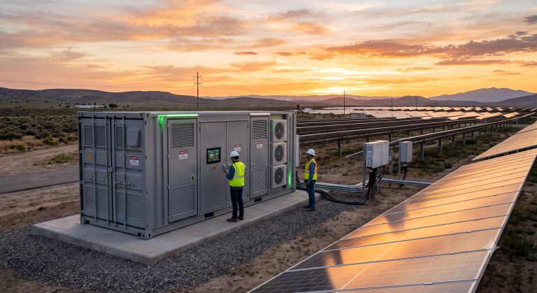
– Commissioning & Integrated Testing: A rigorous commissioning process is mandatory to validate the seamless communication between the EMS, BMS, PCS, PV inverters, and the EV Charging Plug. This involves simulating various grid scenarios (e.g., peak shaving, islanding) to ensure the system responds correctly and safely. End-to-end testing of the charging session initiation, authorization, and termination logic is also essential.
CONCLUSION
The EV Charging Plug is the critical hardware bridge between a facility’s renewable energy assets and the growing fleet of electric vehicles. By integrating it within a sophisticated PV-storage-charging micro-grid, it is no longer just a convenience but a strategic asset. It facilitates peak shaving, enables demand response participation, and, with V2G readiness, unlocks the potential for a truly bi-directional, decentralized energy network. This Reference Design Guide provides the foundational knowledge required to deploy this technology effectively. For detailed technical data, installation manuals, and project-specific engineering support, please consult the full product datasheet or contact our technical sales team.
📥 Download Technical Specification
Click the button below to view or download the full official PDF datasheet.