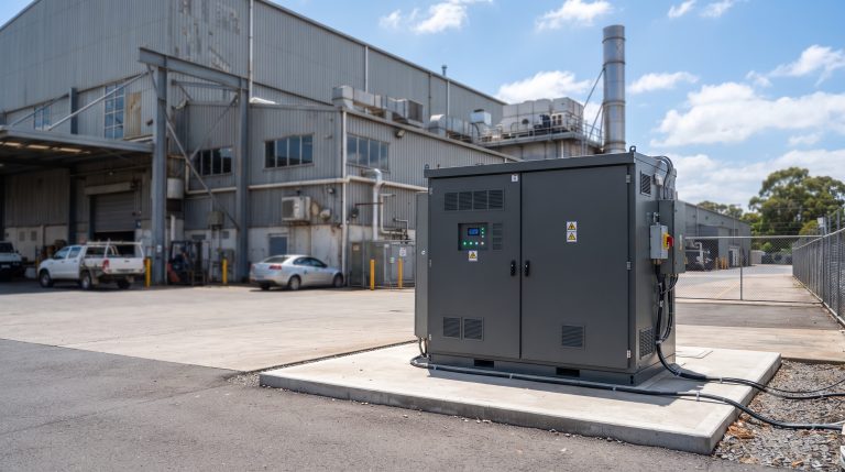
Overview
In utility-scale and commercial BESS, the battery connector is the critical electromechanical interface between cells, modules, and the PCS. It directly impacts system resistance, thermal stability, and long-term reliability. Below are expert answers to the most frequent pre-sales and post-sales questions plant engineers and procurement teams ask about high-current battery connectors.

Frequently Asked Questions
- Q1: What is the standard cycle life and allowable DoD when using high-current battery connectors in LFP-based BESS?
- The standard cycle life exceeds 6,000 cycles at 80% DoD (Depth of Discharge) with proper connector contact resistance below 0.2 mOhm. LFP chemistry paired with silver-plated, multi-leaf spring battery connectors minimizes arc-induced degradation. For optimal lifespan, maintain connector torque specs (typically 8-12 Nm) and perform quarterly infrared scanning to detect early resistance rise.
- Q2: How does the battery connector affect thermal runaway prevention and fire safety in a cabinet?
- The battery connector is the first component to show heat rise before thermal runaway, acting as an early warning sensor. UL 9540A-compliant connectors incorporate flame-retardant housings (UL94 V-0) and integrated temperature sensing pads that trigger BMS shutdown at >105°C. In liquid-cooled systems, connectors must be sealed to IP67 to prevent coolant ingress, which can cause high-resistance hotspots and arc faults.
- Q3: What BMS monitoring parameters are critical for battery connector health in real-time?
- Critical BMS monitoring parameters include per-string contact millivolt drop, differential temperature between connector poles (<3°C alert), and cumulative contact cycles (rated for 100-200 mating cycles). Advanced BMS also tracks partial discharge events and impedance spectroscopy trends. Set alerts when connector resistance exceeds 0.3 mOhm above baseline — this prevents cascading module failures and unplanned downtime.
- Q4: Can I directly scale a modular BESS using the same battery connector for both grid-tie and off-grid islanding configurations?
- Yes, if the connector is rated for the higher fault current of grid-tie mode (typically 10kA for 1 second) and the bidirectional current of off-grid islanding. Use a connector with UL 4128 certification for both applications. For parallel cabinet scalability, employ a keyed, touch-safe DC busbar connector system that maintains polarity alignment and allows hot-swappable module replacement without de-energizing the entire string.
- Q5: How do I calculate ROI improvement when upgrading from legacy bolted lugs to a locking, high-force battery connector?
- Calculate ROI by measuring the reduction in contact resistance: each 0.1 mOhm reduction per 100 kWh saves approximately 1.2% round-trip efficiency. For a 1 MWh system cycling daily at $0.15/kWh arbitrage, upgrading to a precision battery connector yields $6,570 annual savings. Add avoided maintenance costs (bolted lugs require retorquing every 6 months; locking connectors are maintenance-free for 10 years) and ROI is typically under 8 months.
- Q6: What happens if the battery connector fails during a peak shaving event under full load (1C discharge)?
- A failed connector under 1C discharge generates >150°C hotspot within 2 seconds, triggering the BMS over-temperature protection and opening the DC contactor. The string safely isolates within 50 ms. Post-failure, the connector’s housing must be replaced (not just re-terminated) due to spring force relaxation. Always specify connectors with color-changing thermal label indicators for visual post-event inspection.
- Q7: What international standards apply to battery connectors for BESS export (UL 9540, IEC 62619, CE)?
- For UL 9540 compliance, the battery connector must pass the temperature rise test (≤55°C rise at rated current) and short-circuit withstand (10kA). IEC 62619 requires vibration (5 Hz to 500 Hz) and salt spray testing (72 hours minimum). CE marking demands compliance with LV Directive 2014/35/EU for creepage distances and clearance (≥6 mm for 1500V DC systems). Always demand a CB Test Certificate for global acceptance.
- Q8: How do I configure a battery connector for seamless integration with a bi-directional PCS in a PV-storage-charging station?
- Configure a connector with hybrid pin design: silver-plated copper for main power (rated 350A continuous) and two auxiliary signal pins for PCS handshake. When the PCS requests DC charge, the auxiliary pins close 20 ms before main contacts — this pre-charge sequence eliminates inrush arc. For V2G (vehicle-to-grid) applications, choose a connector with 10,000-cycle durability and integrated EMI shielding to prevent inverter noise feedback.