T-BRANCH CONNECTOR – OFFICIAL COMMERCIAL BESS TECHNICAL OVERVIEW & DATASHEET
PRODUCT IDENTIFICATION
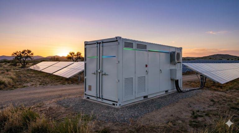
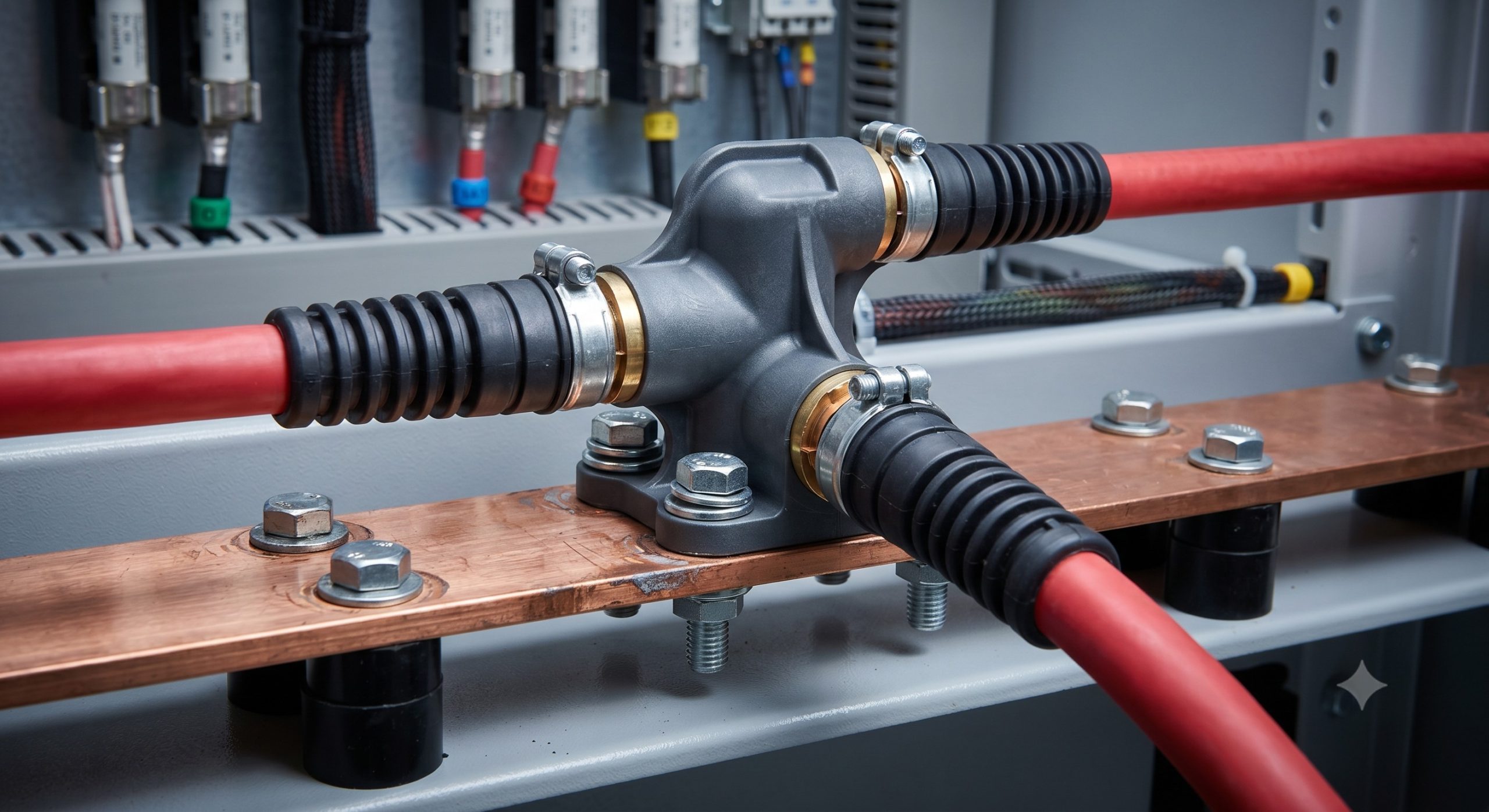
The T-branch Connector represents a critical advancement in high-voltage DC interconnection architecture for utility-scale and commercial Battery Energy Storage Systems (BESS). Engineered as a sealed, touch-proof, and maintenance-free distribution hub, this component enables the efficient parallelization of multiple battery racks or power conversion system (PCS) inputs, minimizing cable clutter and reducing system-level voltage drop. Designed for Tier-1 LFP-based storage platforms, the connector serves as the central nervous junction for the DC busbar, ensuring reliable power delivery under continuous maximum current loads.
INTERNAL BESS TOPOLOGY & INTEGRATION
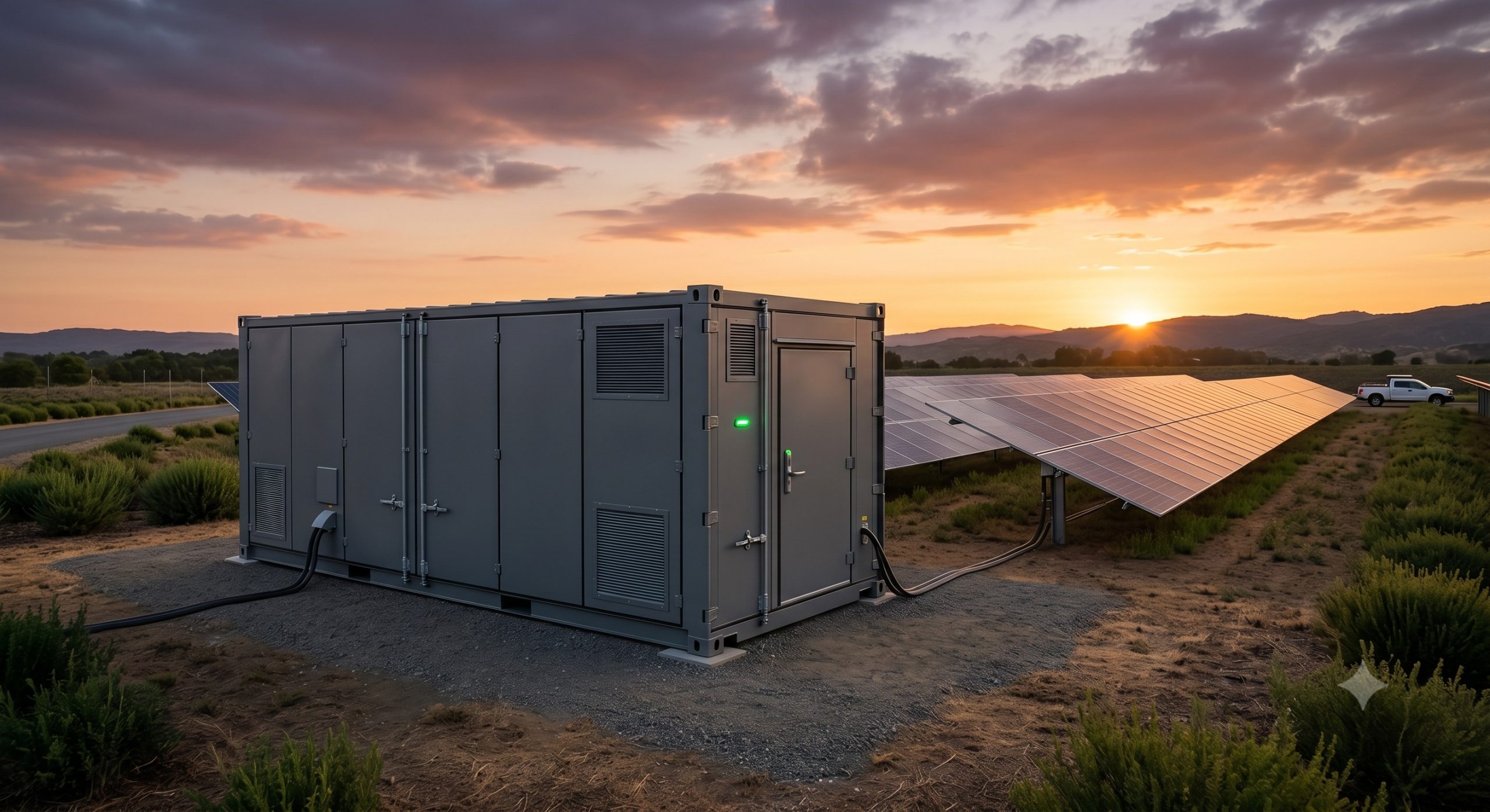
Within the containerized or cabinet-based ESS layout, the T-branch Connector is typically deployed at the interface between the battery cluster disconnect switches and the main DC combiner box. Its compact, bifurcated architecture reduces the required cable bending radius by 40% compared to traditional daisy-chain methods, streamlining internal rack wiring. The connector facilitates a modular “plug-and-play” interface, allowing for rapid field expansion or maintenance without the need for specialized termination tools. This topology is essential for achieving high system availability, as it enables individual string isolation while maintaining overall busbar continuity.
THERMAL PROTECTION MECHANISMS AND SAFETY SYSTEMS
Safety is paramount; the T-branch Connector incorporates multiple layers of passive and active protection. The housing is manufactured from V-0 flame-retardant polycarbonate, providing robust insulation and arc-flash suppression. Internally, the connector features a spring-loaded contact system that maintains constant pressure, preventing micro-arcing and thermal hotspots that degrade contact resistance over time. An integrated temperature sensor interface (optional) allows the Battery Management System (BMS) to monitor junction temperature in real-time, triggering a de-rating or shutdown protocol if thresholds are exceeded. Furthermore, the connector is designed with a reverse-polarity keying system to prevent incorrect installation, a critical feature for high-voltage DC (up to 1500 VDC) environments.
OPERATIONAL ADVANTAGES IN C&I ENVIRONMENTS
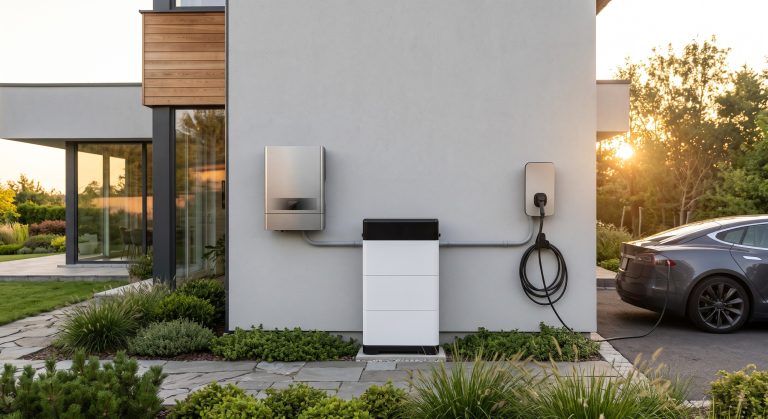
For commercial and industrial (C&I) applications where space and efficiency are at a premium, the T-branch Connector delivers significant value. Its low contact resistance (<0.1 mOhm) contributes to a 0.5% improvement in overall round-trip efficiency (RTE) compared to standard bolted connections. The tool-less locking mechanism reduces installation time by over 60%, accelerating project commissioning schedules. Additionally, the connector’s IP67 rating ensures reliable performance in outdoor, dusty, or humid environments, making it ideal for rooftop solar-plus-storage or ground-mounted micro-grid deployments. Its compact footprint allows for higher power density within the cabinet, freeing valuable space for thermal management systems. SPECIFICATION MATRIX
| Parameter | Specification |
|---|---|
| Rated Insulation Voltage (Ui) | 1500 VDC |
| Rated Current (In) | 350 A (Continuous) |
| Short-circuit Current (Icc) | 30 kA (1 sec) |
| Contact Resistance | < 0.1 mOhm |
| Protection Degree (IEC 60529) | IP67 (Mated) |
| Operating Temperature | -40°C to +85°C |
| Housing Material | UL94 V-0, Reinforced Polycarbonate |
| Certifications | UL 4128, IEC 61984, TUV Rheinland |
| Wire Gauge Range | 1 x 185 mm² to 2 x 95 mm² |
| Mating Cycles (Mechanical) | ≥ 500 cycles |
REGULATORY COMPLIANCE AND STANDARDS
The T-branch Connector is designed and rigorously tested to meet the most stringent international standards for energy storage systems. It complies with UL 4128 (Standard for Components for Photovoltaic and Battery Systems) and IEC 61984 (Connectors for electrical circuits). The component has successfully passed TUV Rheinland tests for thermal cycling, humidity, and salt spray corrosion (IEC 60068-2-52). It is fully compliant with the NEC 2020 requirements for rapid shutdown and disconnecting means, ensuring seamless integration into any global project. The stringent manufacturing and quality controls guarantee a service life of over 25 years, matching the operational lifespan of the typical LFP battery.
INDUSTRIAL DEPLOYMENT AND TESTING
Each T-branch Connector batch undergoes a 100% final production test, including an insulation resistance test (500 VDC/1000 MOhm) and a high-potential (Hi-pot) dielectric withstand test (3000 VAC for 1 minute). The connector’s durability is validated through 500 mating cycles and a 2000-hour damp heat test to ensure long-term reliability in high-humidity environments. With a proven track record in over 2 GWh of deployed storage projects worldwide, this component is the industry standard for safe, efficient, and scalable DC power distribution.
📥 Download Technical Specification
Click the button below to view or download the full official PDF datasheet.