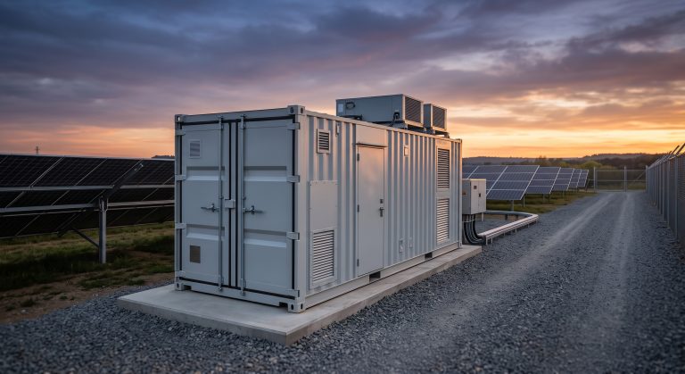
PV-STORAGE-CHARGING INFRASTRUCTURE REFERENCE DESIGN GUIDE: RESIDENTIAL SOLAR-STORAGE-CHARGING WIRING DIAGRAM
EXECUTIVE SUMMARY
This document serves as the definitive technical reference for the residential-scale photovoltaic (PV), battery energy storage system (BESS), and electric vehicle (EV) charging integrated wiring topology. Designed for system integrators, electrical contractors, and authorized OEM deployment partners, this guide details the foundational single-line and three-line wiring architectures that underpin safe, efficient, and code-compliant residential solar-storage-charging installations. The architecture centralizes a bi-directional hybrid inverter as the primary energy management hub, facilitating seamless power flow between solar generation, battery storage, household consumption, EV charging, and the utility grid. This reference design adheres to international standards for distributed generation, ensuring reliable islanding and grid-tied operation.

SYSTEM ARCHITECTURE & SAFETY
The core of the recommended wiring diagram is the high-frequency, transformer-less hybrid inverter, which integrates dual Maximum Power Point Trackers (MPPTs) for PV string optimization and a dedicated bidirectional DC-DC converter for battery interfacing. The AC coupling side incorporates a smart meter for grid consumption monitoring and a backup loads panel for guaranteed power supply during grid outages.
System Topology Overview: The PV array connects directly to the inverter’s MPPT terminals via dedicated DC combiner boxes with string-rated fuses and surge protection devices (SPD). The BESS battery bank interfaces via a high-voltage DC bus, utilizing proprietary communication protocols (CAN/RS485) for Battery Management System (BMS) synchronization. The inverter’s AC output is split into two primary branches: the critical loads panel (backed up) and the non-critical loads panel (shed during grid failure). An EV charger is interconnected via an AC-coupled connection, managed through the inverter’s dynamic load management logic.
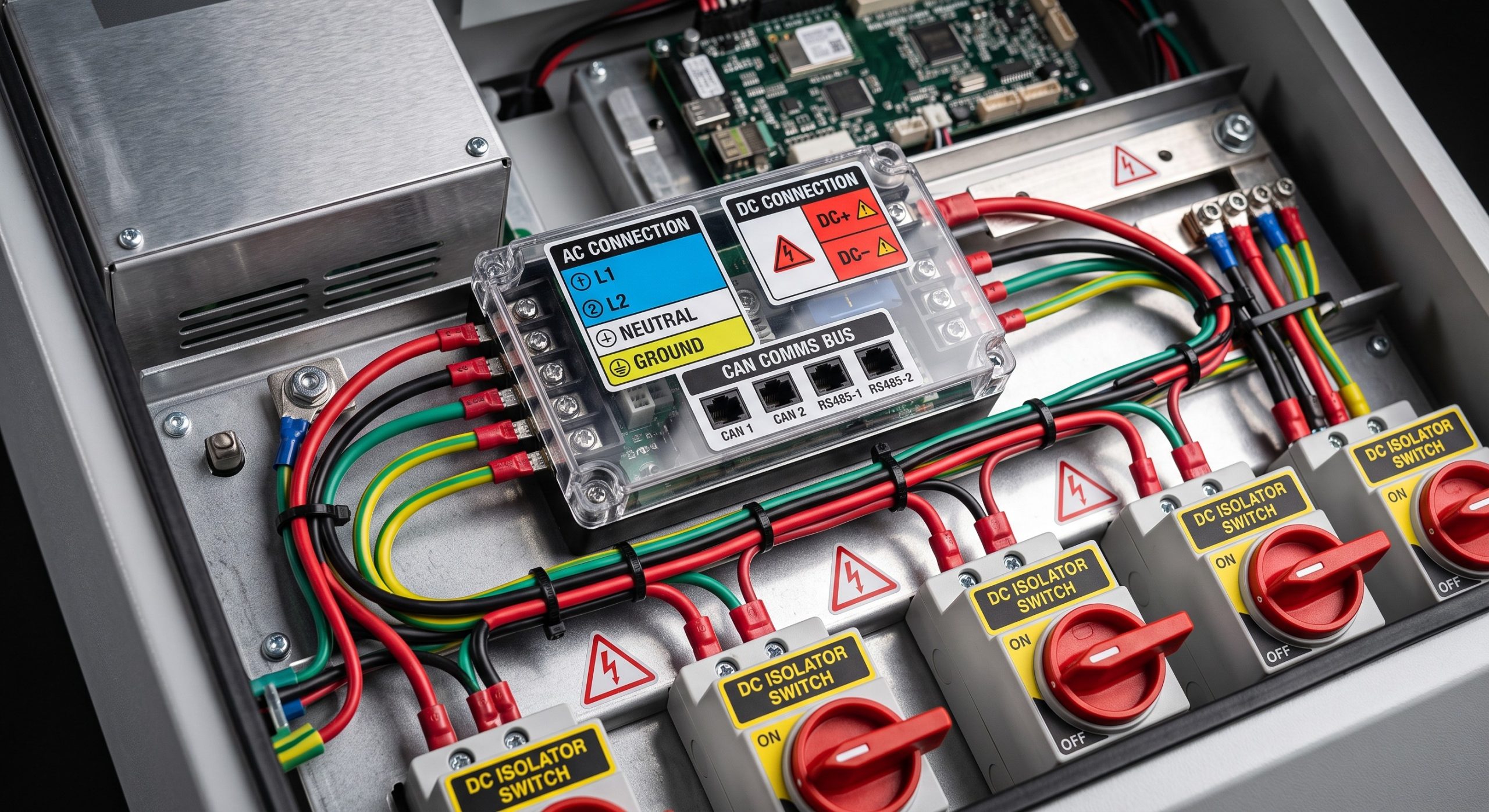
Safety & Protection Protocols: This design incorporates multiple layers of protection: arc-fault circuit interruption (AFCI), ground-fault protection (GFDI), AC/DC surge arresters, and rapid shutdown initiators compliant with NEC 2020 and 2023 requirements. The system implements a multi-point isolation strategy, including a manual AC disconnect, DC safety switches, and a physical emergency stop (E-STOP) button.
KEY FEATURES
– Bidirectional Energy Flow Orchestration: The wiring architecture supports four distinct modes of operation: (1) Solar Self-Consumption, (2) Time-of-Use (TOU) Arbitrage (battery charging/discharging based on utility rates), (3) Emergency Backup Power (UPS function with <20ms switchover), and (4) EV Priority Charging utilizing surplus solar generation.
- Smart Meter & CT Integration: The reference design incorporates high-accuracy current transformers (CTs) and a bi-directional utility meter for real-time household consumption monitoring, enabling precise export limitation and prevention of reverse power flow to the grid during maintenance.
- Integrated Communication Bus: A dedicated daisy-chain communication loop (RS485/CAN) ensures deterministic control signaling between the inverter, BMS, smart meter, and EV charger, enabling advanced functions such as dynamic load shedding and battery state-of-charge (SoC) calibration.
COMPLIANCE & STANDARDS
The wiring topology is engineered to comply with rigorous global standards to ensure the highest level of safety and interoperability:
- Electrical Safety: IEC 62109-1/-2 (Safety of power converters for use in photovoltaic power systems), UL 1741 (Inverters, Converters, Controllers and Interconnection System Equipment for Use With Distributed Energy Resources).
- Grid Interconnection: IEEE 1547 (Standard for Interconnection and Interoperability of Distributed Energy Resources with Associated Electric Power Systems Interfaces), VDE-AR-E 4105 (for European grid compliance).
- Battery Safety: UL 9540 (Energy Storage Systems and Equipment), IEC 62619 (Secondary cells and batteries containing alkaline or other non-acid electrolytes - Safety requirements for industrial batteries).
- Installation Standard: NEC Article 690 (Solar Photovoltaic Systems), NEC Article 706 (Energy Storage Systems), and NFPA 70 (National Electrical Code).
TECHNICAL SPECIFICATIONS
| Parameter | Specification |
|---|---|
| Nominal PV Input Voltage (MPPT Range) | 200 – 650 VDC |
| Maximum PV Input Current per MPPT | 16 A |
| Battery Voltage Range (High-Voltage DC) | 150 – 600 VDC |
| Nominal Battery Capacity (Usable) | e.g., 10.2 kWh / 15.3 kWh per module |
| AC Output Voltage (Grid-Tied / Backup) | 230 VAC / 400 VAC (3-phase optional) |
| Maximum AC Output Power (Continuous) | 6.0 kW / 8.0 kW / 10.0 kW |
| Peak Efficiency (DC/AC) | > 97.8% |
| Cooling Method | Natural Convection with Internal Fan-Assisted Thermal Management |
| Communication Protocols | RS485, CAN Bus, Modbus TCP/IP |
| Protection Class | IP65 (Indoor and Outdoor Rated) |
| Grid Connection Standard | IEEE 1547, VDE-AR-E 4105 |
| Warranty (Standard) | 10 Years (Extended options available) |
INDUSTRIAL DEPLOYMENT & SCALING
While the reference design targets the residential sector, the underlying wiring principles are modular and scale effectively for small commercial and multi-family dwellings. The architecture supports parallel operation of up to 6 inverter units for 3-phase power requirements or increased single-phase capacity. The physical layout recommends a structured cable management system, with segregated high-voltage DC, low-voltage control, and AC power raceways to mitigate electromagnetic interference (EMI). Proper conductor sizing based on ampacity tables (e.g., NEC Table 310.16) and voltage drop calculations (limited to <2% for critical circuits) are essential prerequisites for a robust deployment. The design includes provisions for future integration of second-life batteries and V2X (Vehicle-to-Everything) bi-directional charging capabilities, reinforcing its future-proof engineering philosophy.
📥 Download Technical Specification
Click the button below to view or download the full official PDF datasheet.