PRODUCT IDENTIFICATION
The Energy Storage Auxiliary Power Wiring Guide constitutes a critical engineering sub-system within the broader commercial and industrial (C&I) battery energy storage platform. This reference manual establishes the authoritative wiring methodology, protection coordination, and interconnection logic for all auxiliary loads internal to the ESS cabinet, including but not limited to: thermal management loops, fire suppression actuation circuits, battery management system (BMS) power rails, environmental control instrumentation, and communication gateway power feeds. The guide is written for certified installation engineers, commissioning specialists, and licensed electrical contractors operating under OEM-approved procedures.
The auxiliary power architecture is deliberately isolated from the main DC bus and AC grid-tied power stage to guarantee that safety-critical functions remain operational during grid outages, islanding events, or main breaker trips. All auxiliary circuits are fed from a dedicated internal auxiliary transformer or an external UPS-backed distribution panel, as dictated by site topology.
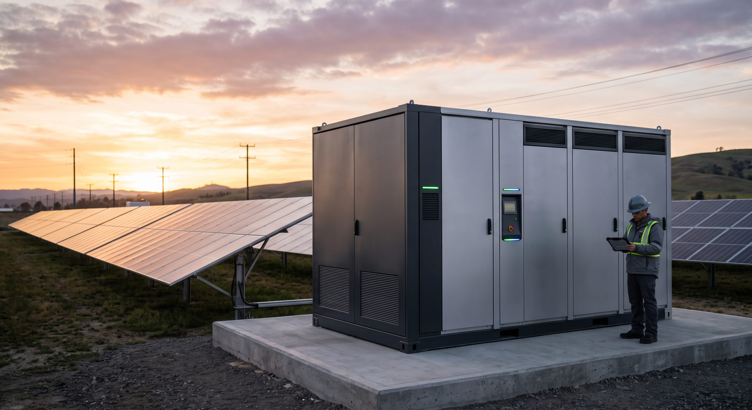
INTERNAL BESS TOPOLOGY AND AUXILIARY POWER DISTRIBUTION
The auxiliary power system within the ESS cabinet is structured in a three-tier distribution hierarchy:
Tier 1 — Primary Auxiliary Bus: Fed from a 400 VAC / 480 VAC three-phase supply derived either from the grid-side point of common coupling (PCC) or from an external diesel generator / UPS. This bus supplies the liquid cooling unit compressors, cabinet-level HVAC (where applicable), and the main EMS server rack.
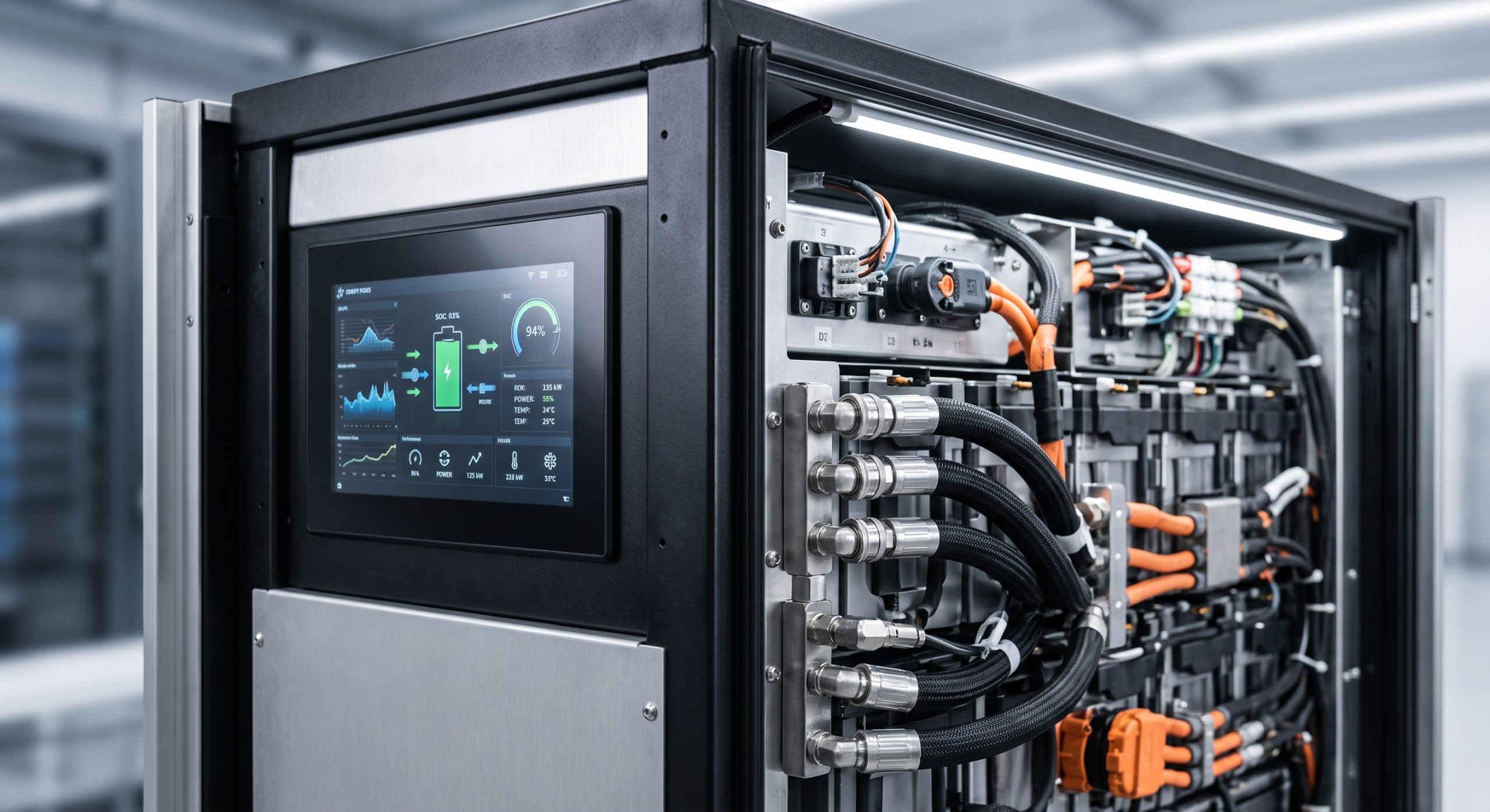
Tier 2 — Control and Safety Bus: A 24 VDC nominal rail derived from redundant AC/DC rectifiers with a battery back-up module. This rail exclusively powers the BMS master controller, cell monitoring units (CMUs), fire detection panel, gas sensors, and emergency stop logic. Redundancy is mandatory: dual rectifiers with automatic load sharing and a 30-minute minimum autonomy battery pack.
Tier 3 — Instrumentation and Communication Bus: A 12 VDC / 5 VDC regulated supply for sensors (temperature, humidity, smoke, differential pressure), dry-contact relays, and communication gateways (Modbus TCP, CAN bus repeaters, Ethernet switches). This tier is galvanically isolated from Tier 1 and Tier 2 to prevent common-mode noise coupling into measurement circuits.
All auxiliary wiring shall be routed in dedicated metallic conduits or segregated cable trays, physically separated from high-voltage DC busbars (minimum 300 mm clearance) and AC power cables. Shielded twisted-pair cables are mandatory for all analog sensor and communication lines. Shield grounding shall be single-point at the cabinet PE bar.
| Parameter | Specification |
|---|---|
| Auxiliary Input Voltage (AC) | 400 VAC / 480 VAC, 3-phase, 50/60 Hz |
| Auxiliary Control Voltage (DC) | 24 VDC nominal (18–30 VDC operating range) |
| Backup Autonomy | 30 minutes minimum for BMS and fire panel |
| Auxiliary Transformer Rating | 10 kVA (typical per cabinet) |
| Wiring Insulation Rating | 0.6/1 kV, XLPE or LSZH |
| Min. Conductor Size (Power) | 2.5 mm² (14 AWG) |
| Min. Conductor Size (Signal) | 0.75 mm² (18 AWG) shielded |
| Separation Distance (HV vs LV) | ≥ 300 mm |
| Ingress Protection (Junction Boxes) | IP54 minimum |
| Compliance | IEC 60364, UL 508A, UL 9540, NFPA 855 |
REGULATORY COMPLIANCE AND WIRING STANDARDS
All auxiliary power wiring must comply with the following international and regional standards:
– IEC 60364-5-52: Low-voltage electrical installations — Wiring systems
– IEC 61439-1 / -2: Low-voltage switchgear and controlgear assemblies
– UL 508A: Industrial Control Panels
– UL 9540: Energy Storage Systems and Equipment
– NFPA 70 (NEC) Article 706: Energy Storage Systems
– NFPA 855: Standard for the Installation of Stationary Energy Storage Systems
– IEC 62619: Secondary cells and batteries containing alkaline or other non-acid electrolytes — Safety requirements for industrial batteries
Auxiliary circuit conductors shall be sized with a minimum 125% ampacity margin over continuous load current. Overcurrent protection devices (OCPDs) must be coordinated with the ESS main protection scheme to avoid nuisance tripping during grid transients. All field wiring terminals shall be torque-marked and verified per OEM torque tables. Wire color coding shall follow IEC 60446 or local code, with distinct colors for DC auxiliary power (red/blue), AC auxiliary power (brown/black/grey), and safety interlock circuits (yellow/green or orange).
📥 Download Technical Specification
Click the button below to view or download the full official PDF datasheet.