Introduction: The Thermal Bottleneck in Modern C&I Energy Storage
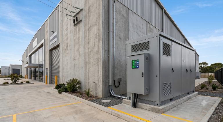
As commercial and industrial (C&I) facilities increasingly deploy Battery Energy Storage Systems (BESS) to manage peak demand charges and integrate renewable generation, the energy storage inverter integration strategy has emerged as the single most critical determinant of system longevity, safety, and return on investment. While much attention is paid to cell chemistry and capacity sizing, the thermal management architecture—specifically the choice between liquid cooling and air cooling—fundamentally governs the operational envelope of the entire system.
Industrial-scale energy storage systems ranging from 500 kWh to 5 MWh generate substantial internal heat during high-rate charge and discharge cycles. The Power Conversion System (PCS), which performs bi-directional DC-AC conversion, and the battery modules themselves are the primary heat sources. If thermal energy is not efficiently dissipated, the consequences cascade: accelerated State of Health (SOH) degradation, reduced Round-trip Efficiency (RTE), and in worst-case scenarios, thermal runaway propagation. This deep technical review examines the engineering trade-offs between liquid and air cooling methodologies within the context of energy storage inverter integration, providing system architects and procurement engineers with the data-driven insights necessary to optimize thermal efficiency for Tier-1 LFP-based commercial ESS deployments.
Core Architecture: PCS and BMS Integration in Thermal Management
The Role of the Power Conversion System (PCS) in Heat Generation
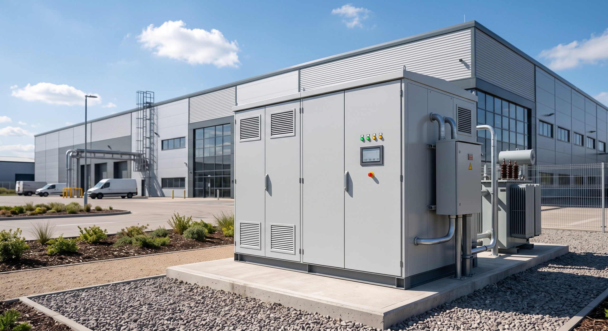
The PCS is the heart of any commercial energy storage system, responsible for converting DC power from the battery bank to grid-compatible AC power and vice versa. During this bi-directional conversion process, switching losses in the IGBT or SiC power semiconductors generate significant heat. A typical 100 kW PCS operating at 98% efficiency still dissipates approximately 2 kW of thermal energy as waste heat. In high-density cabinet configurations where multiple PCS units are co-located with battery modules, this heat load compounds rapidly.
Effective energy storage inverter integration requires that the thermal management system not only cool the battery cells but also manage PCS heat dissipation without creating thermal gradients that imbalance the system. Liquid cooling plates integrated directly onto PCS power modules can maintain junction temperatures below 85°C, whereas air-cooled designs may experience hot spots exceeding 105°C under continuous full-load operation, triggering derating and reducing usable capacity.
Battery Management System (BMS) and Cell Balancing Under Thermal Stress
The BMS serves as the central nervous system of the ESS, continuously monitoring cell voltage, temperature, and state of charge (SOC). In air-cooled systems, temperature differentials across a battery rack can exceed 8-10°C, causing unbalanced aging rates between cells. The BMS must then expend additional energy on active balancing, further reducing Round-trip Efficiency. In contrast, liquid-cooled architectures achieve temperature differentials of less than 3°C across the entire rack, enabling the BMS to maintain cells within a tight 25-35°C operating window—the optimal range for Tier-1 LFP chemistry.
This thermal uniformity directly impacts Depth of Discharge (DoD) capability. A thermally balanced system can safely operate at 90% DoD without accelerating degradation, whereas an air-cooled system with hot spots may be limited to 80% DoD to prevent localized over-discharge. For a 1 MWh system, this 10% difference represents 100 kWh of unusable capacity—a significant economic penalty over a 10-year operational life.
Technical Specifications: Thermal Performance Metrics
The following specification ledger compares key thermal and electrical parameters for liquid-cooled versus air-cooled commercial ESS configurations. These metrics represent typical Tier-1 system capabilities and should be validated against specific manufacturer datasheets during procurement.
| Key Parameter | Liquid-Cooled ESS Specification | Air-Cooled ESS Specification |
|---|---|---|
| Battery Chemistry | Tier-1 LFP (Lithium Iron Phosphate) | Tier-1 LFP (Lithium Iron Phosphate) |
| System Capacity Range | 500 kWh – 5 MWh (modular) | 100 kWh – 1 MWh (modular) |
| Cycle Life | >8,000 cycles @ 90% DoD, 25°C | >6,000 cycles @ 80% DoD, 25°C |
| Round-trip Efficiency | ≥92% (AC-AC) | ≥88% (AC-AC) |
| Depth of Discharge (DoD) | 90% (continuous) | 80% (continuous) |
| Operating Temperature Range | -20°C to +55°C (with derating above 45°C) | -10°C to +45°C (with derating above 35°C) |
| Temperature Uniformity (ΔT) | <3°C across rack | <8-10°C across rack |
| Thermal Management Parasitic Load | 2-4% of rated capacity | 1-2% of rated capacity |
| PCS Junction Temperature | <85°C at full load | <105°C at full load |
| Cooling Medium | Glycol-water mixture (50/50) | Forced air (high-CFM fans) |
| Fire Suppression Integration | Multi-level: aerosol + NFPA 855 + gas detection | Standard: aerosol + smoke detection |
| Compliance & Certification | UL 9540, IEC 62619, UN38.3, CE | UL 9540, IEC 62619, UN38.3, CE |
| Footprint (per MWh) | ~15-20 m² | ~25-35 m² |
| Design Life | 15 years | 10 years |
| Warranty (Typical) | 10 years / 8,000 cycles | 5-7 years / 6,000 cycles |
Thermal Control Deep Dive: Liquid vs. Air Cooling
Liquid Cooling: Precision Thermal Regulation
Liquid cooling systems circulate a glycol-water mixture through cold plates mounted directly beneath or between battery modules. The high thermal conductivity of the liquid medium—approximately 25 times greater than air—enables rapid heat extraction even under high C-rate operation. Advanced liquid cooling architectures incorporate variable-speed pumps and smart flow control valves that modulate coolant flow based on real-time BMS temperature data, optimizing parasitic power consumption.
The parasitic load of a liquid cooling system typically ranges from 2-4% of total system capacity, which is higher than air cooling’s 1-2%. However, this energy penalty is more than offset by the 2-3% improvement in Round-trip Efficiency and the extended cycle life resulting from superior thermal uniformity. For a 2 MWh system cycling once daily, the net energy savings can exceed 15,000 kWh annually.
Air Cooling: Simplicity and Cost Efficiency
Air cooling relies on forced convection through high-CFM fans and carefully designed air ducts to remove heat from battery modules and PCS components. The primary advantages are lower upfront cost, simpler maintenance, and reduced system complexity. Air-cooled systems are well-suited for moderate climates and lower-duty-cycle applications where peak ambient temperatures rarely exceed 35°C.
However, air cooling faces fundamental thermodynamic limitations. As ambient temperatures rise, the cooling capacity diminishes precisely when the system needs it most. During summer peak demand periods—when peak shaving value is highest—air-cooled systems may derate to 80-85% of rated capacity to prevent overheating. This derating directly undermines the peak shaving ROI that justified the ESS investment. Additionally, air-cooled systems require regular filter replacement and duct cleaning, adding to O&M costs over the system lifetime.
Hybrid Approaches and Emerging Technologies
Some advanced energy storage inverter integration designs employ hybrid thermal management strategies, using liquid cooling for the battery modules and air cooling for the PCS and auxiliary electronics. This approach balances cost and performance, allocating the more expensive liquid cooling infrastructure where it delivers the greatest benefit. Emerging technologies such as two-phase immersion cooling and thermoelectric cooling are being evaluated for next-generation high-density systems, though commercial maturity remains limited.
Commercial ROI and Grid Support Implications
Peak Shaving Economics Under Thermal Constraints
The primary economic driver for C&I energy storage remains peak shaving—discharging stored energy during high-tariff periods to reduce demand charges. A thermally constrained system that derates during peak hours delivers less value precisely when the economics are most favorable. For a facility with a $25/kW monthly demand charge and a 500 kW peak, a 10% derating during summer months translates to $1,250 in lost monthly savings per year.
Liquid-cooled systems maintain full rated power output across a wider ambient temperature range, ensuring that the Levelized Cost of Storage (LCOS) remains predictable and favorable. When modeling Total Cost of Ownership (TCO) over a 10-year horizon, the higher upfront cost of liquid cooling is typically recovered within 3-5 years through superior performance and extended asset life.
Grid Support and Frequency Regulation
Beyond peak shaving, commercial ESS assets can participate in demand response programs and provide frequency regulation services. These applications require rapid, high-power charge/discharge cycles that generate intense thermal loads. Liquid-cooled systems are inherently better suited to these high-stress duty cycles, maintaining Round-trip Efficiency above 90% even under aggressive cycling regimes. Air-cooled systems may struggle to sustain the required power output without thermal derating, limiting their eligibility for premium grid service revenue streams.
Safety and Compliance
Thermal management is inseparable from system safety. UL 9540 and IEC 62619 standards mandate rigorous thermal propagation testing to ensure that a single cell failure does not cascade into a full system fire. Liquid cooling systems, with their ability to rapidly extract heat from a failing cell, provide a critical layer of defense. When integrated with multi-level fire suppression systems—including aerosol agents, NFPA 855-compliant suppression, and gas detection—liquid-cooled ESS architectures achieve the highest safety ratings. UN38.3 transportation certification and CE marking further validate the system’s ability to withstand thermal and mechanical stresses during global deployment.
Deployment Scenarios: Matching Thermal Strategy to Application
Industrial Parks and Manufacturing Facilities
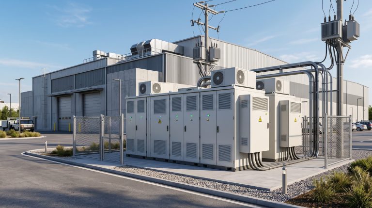
Industrial parks with high simultaneous load factors and limited grid capacity are ideal candidates for liquid-cooled ESS integration. The ability to maintain full power output during peak shifts, combined with the compact footprint of high-density liquid-cooled cabinets, maximizes the value of available installation space. Modular cabinet expansion allows facilities to scale capacity incrementally as production grows.
EV Supercharging Stations
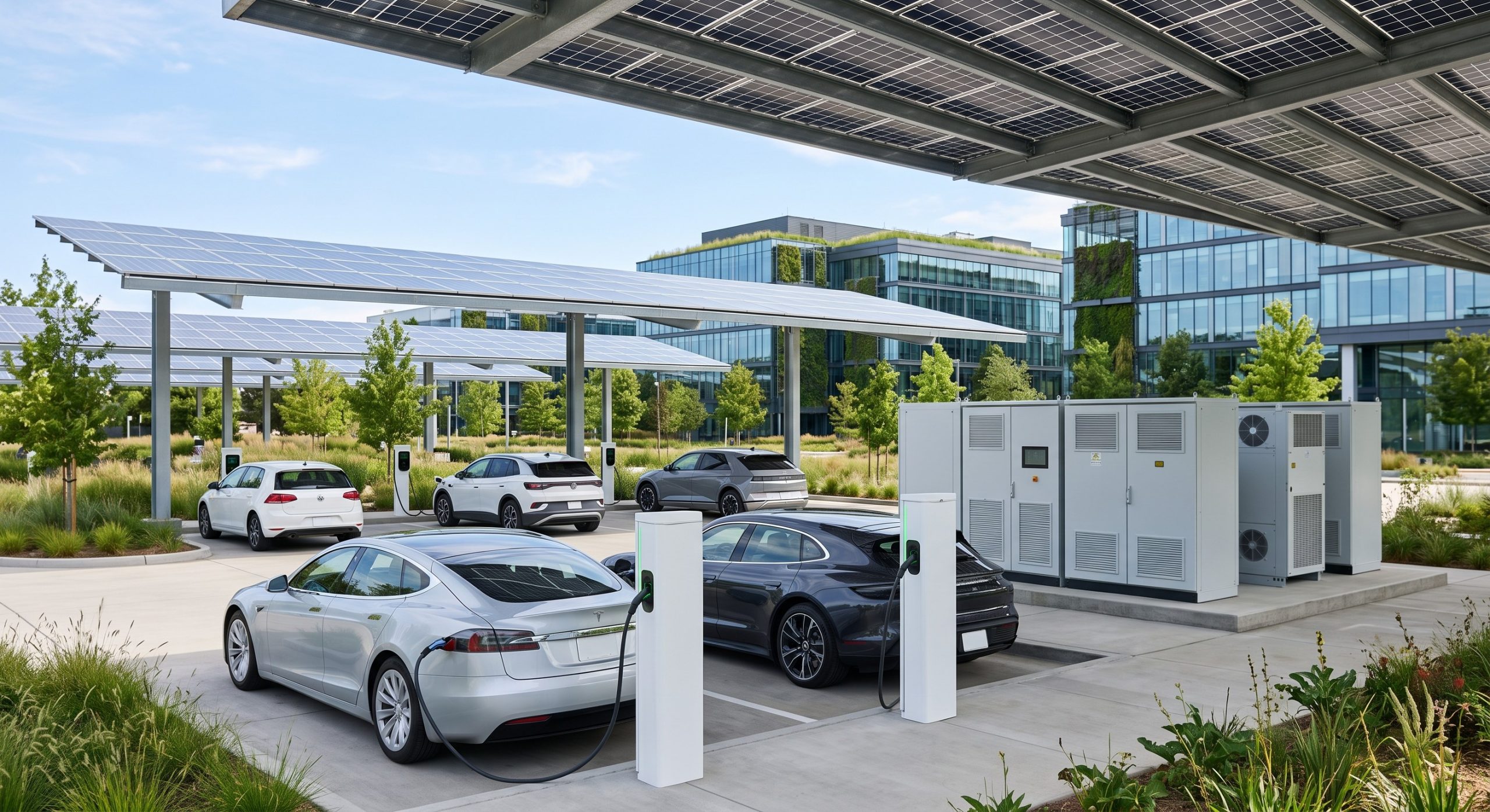
The integration of PV-Storage-Charging (光储充) infrastructure at EV supercharging stations presents unique thermal challenges. High-power DC fast chargers impose sudden, intense loads on the ESS, demanding rapid discharge rates that generate significant heat. Liquid-cooled systems are essential in this application, maintaining PCS junction temperatures within safe limits while supporting 350 kW+ charging sessions. The synergy between solar canopies, battery storage, and fast charging creates a self-sustaining energy ecosystem that reduces grid dependency and operational costs.
Data Centers and Mission-Critical Facilities
Data centers require 99.999% uptime and cannot tolerate thermal-related derating or downtime. Liquid-cooled ESS provides the thermal headroom necessary for seamless grid-to-off-grid transition during utility outages, ensuring that critical IT loads remain powered without interruption. The high Round-trip Efficiency of liquid-cooled systems also reduces the total energy overhead of the backup power system, contributing to sustainability goals.
Conclusion: Strategic Thermal Architecture for Long-Term Asset Value
The choice between liquid cooling and air cooling in energy storage inverter integration is not merely a technical detail—it is a strategic decision that impacts system performance, safety, longevity, and financial returns over a 10-15 year operational life. While air-cooled systems offer lower initial CapEx and simpler maintenance for moderate-duty applications, liquid-cooled architectures deliver superior thermal uniformity, higher Round-trip Efficiency, extended cycle life, and enhanced safety compliance.
For C&I facility owners, EPC contractors, and system integrators evaluating BESS wholesale procurement, the data is clear: the incremental upfront investment in liquid cooling is consistently justified by improved peak shaving ROI, eligibility for premium grid services, and reduced long-term O&M costs. As LFP cell technology continues to advance toward 10,000+ cycle warranties, the thermal management system becomes the limiting factor in realizing that potential. Selecting a Tier-1 liquid-cooled ESS platform with certified UL 9540 and IEC 62619 compliance is not just a procurement decision—it is a commitment to operational excellence and sustainable energy independence.