COMMERCIAL SYSTEMS ENGINEERING REFERENCE MANUAL: BESS ERROR CODE & TROUBLESHOOTING GUIDE
1. EXECUTIVE SUMMARY
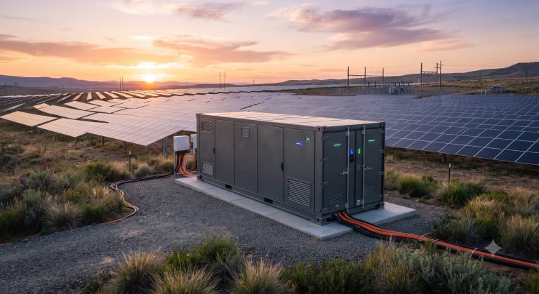
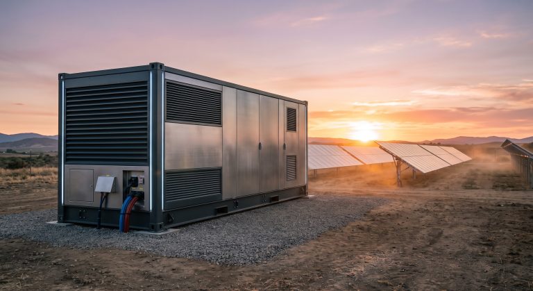
This document serves as the definitive technical reference for diagnosing, interpreting, and resolving system-level alerts and fault conditions within our advanced Battery Energy Storage System (BESS) platform. Designed for utility-scale and commercial & industrial (C&I) deployments, this guide provides engineering personnel with a structured methodology for fault identification, root cause analysis, and corrective action execution. The error code framework integrates seamlessly with the Battery Management System (BMS), Power Conversion System (PCS), and Energy Management System (EMS) to deliver unparalleled diagnostic precision and system uptime. All procedures outlined herein align with UL 9540, IEC 62933, and local grid interconnection requirements, ensuring safe and compliant operations.
2. SYSTEM ARCHITECTURE & SAFETY INTERLOCKS
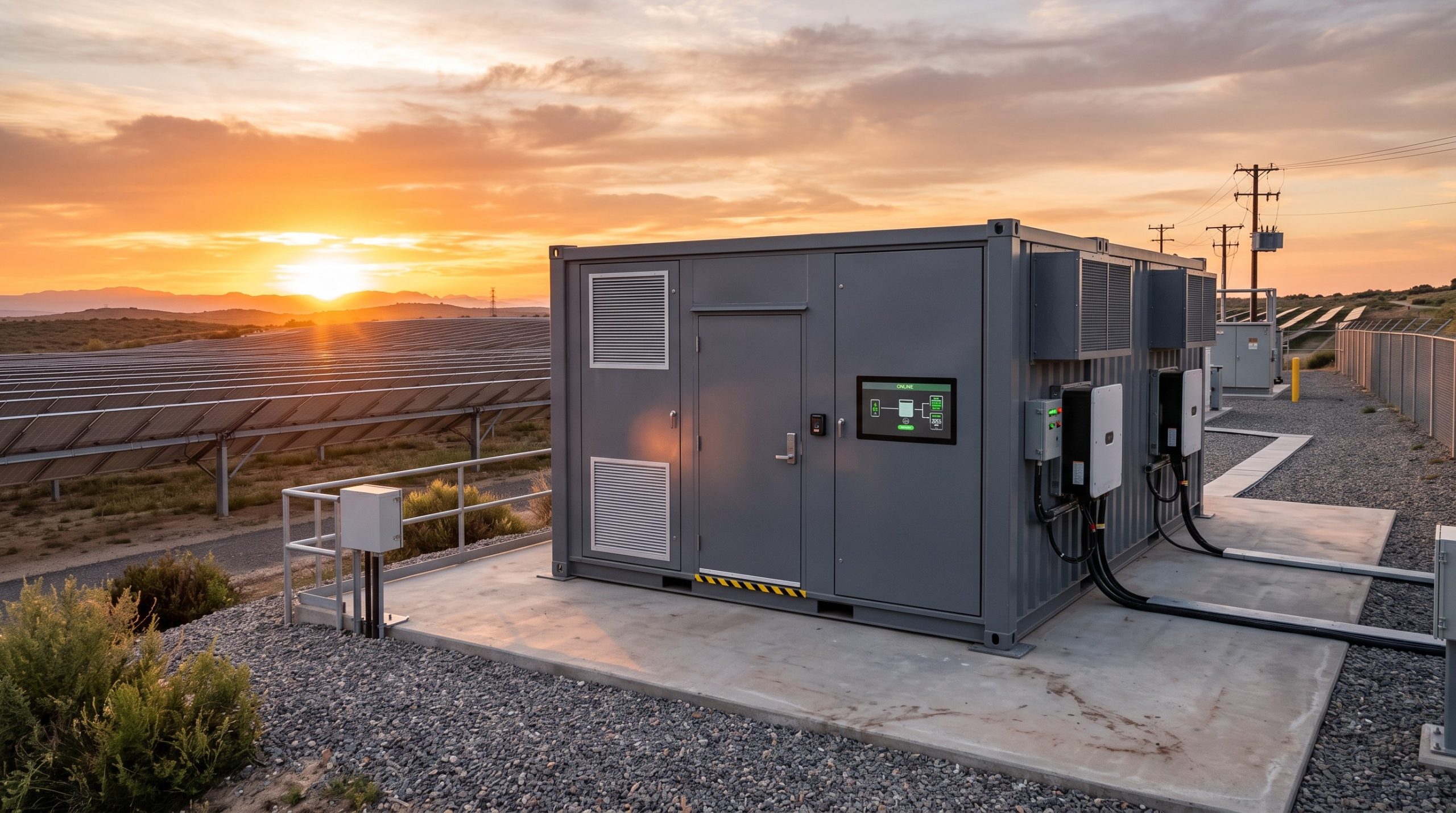
The fault monitoring hierarchy is structured across three primary control layers. The BMS provides cell-level protection, monitoring voltage, temperature, and state-of-charge (SoC) with millisecond response times. The PCS manages power flow and grid synchronization, while the EMS coordinates the overall dispatch logic and system health at the plant level. A multi-tiered safety interlock system (Software, Hardware, and Firmware-based) ensures that any critical error triggers a controlled system shutdown or derating to prevent thermal or electrical incidents. The diagnostic interface (local HMI or remote SCADA) displays errors using a standardized alphanumeric code structure for rapid identification.
3. DIAGNOSTIC PROTOCOLS & TROUBLESHOOTING MATRIX
The comprehensive troubleshooting matrix below details the most common error codes. The table provides the primary error code, the originating subsystem, the potential root cause, and the recommended standard corrective actions. This protocol ensures a rapid and uniform response across global service teams, minimizing Mean Time To Repair (MTTR).
| ERROR CODE | SUBSYSTEM | DESCRIPTION / CAUSE | TROUBLESHOOTING ACTION |
|---|---|---|---|
| E-CELL-01 | BMS | Cell Overvoltage (>3.65V). Typically caused by an imbalanced cell or aggressive charging profile. | Stop charging. Perform passive or active cell balancing via BMS software. Verify charge voltage settings. |
| E-CELL-45 | BMS | Cell Undervoltage (<2.5V). Often due to deep discharge, cell degradation, or high self-discharge. | Isolate the affected module. Test for internal shorts. Recharge the entire string with a low current (0.1C) to attempt recovery. |
| E-TEMP-23 | BMS/COOL | Battery Module Overtemperature (Grade 2). Exceeding 55°C. Potential causes: coolant system failure, blocked vents, or high ambient temperature. | Check coolant flow rate and temperature set point. Inspect cooling pipes for blockages and ensure fans are operational. System will derate power. |
| E-ISO-12 | PCS/BMS | Ground Fault / Insulation Resistance Low (<1 MOhm). Indicates moisture ingress or damaged cable insulation in the DC bus. | Immediately stop operation. Use an insulation resistance tester (megger) to locate the faulty circuit or cable. Allow system to dry or replace damaged cabling. |
| E-PCS-77 | PCS | Grid Over-Frequency (OFR). Grid frequency has exceeded the local grid code limit (e.g., >50.2Hz). | System enters standby. No action required unless the condition persists. If persistent, verify the grid code settings and utility transformer specifications. |
| E-EMS-88 | EMS | Communication Timeout (Modbus/CAN). Lost connection between EMS and BMS/PCS. | Check ethernet/RS485 cabling and terminations. Verify IP addresses and network switches. Perform a soft reset of the EMS gateway. |
| E-COMM-52 | BMS | CAN Bus Communication Error or CRC Check Failure. | Check the CAN bus termination resistors (120 Ohms). Verify the baud rate configuration. Look for electrical noise sources near the communication cables. |
4. ADVANCED COMMUNICATION AND DIAGNOSTIC LOGIC
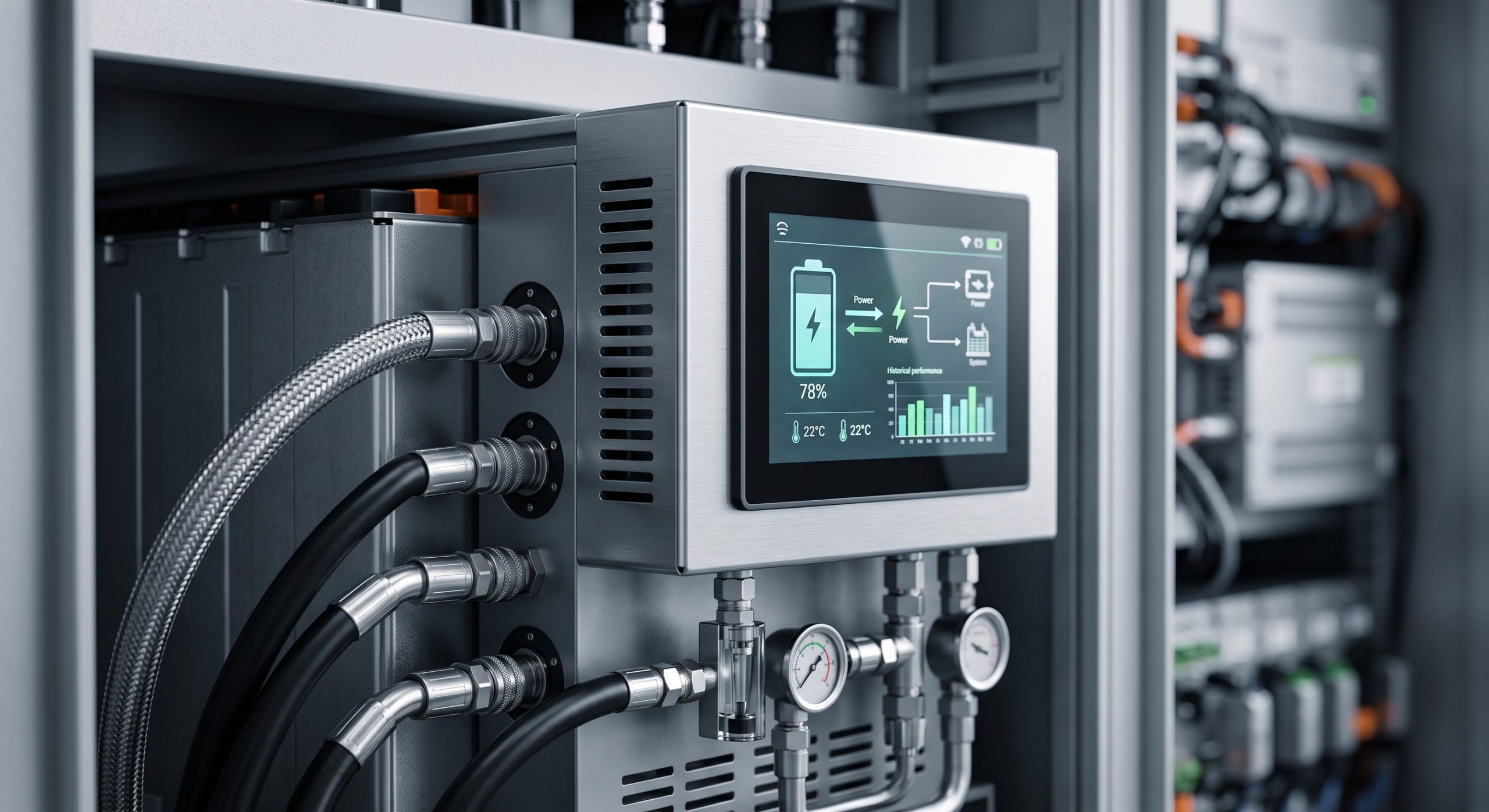
Beyond the standard fault codes, the system integrates a predictive diagnostic algorithm that analyzes historical data trends to forecast potential failures. This feature allows for proactive maintenance interventions prior to a fault occurrence. For persistent or high-severity faults (e.g., Isolation Faults or High Temperature, Grade 1), the system will initiate an automated data logging procedure, capturing a high-resolution waveform of the PCS output and BMS cell voltages for post-event analysis by our remote engineering team. Users can access the live event log and diagnostic data via the EMS web portal or the local touchscreen interface.
5. GRID INTERCONNECTION & ISLANDING FAULT RESPONSE
The PCS is equipped to handle various grid disturbances (e.g., under/over frequency, voltage sag/swell). The error codes in the “Grid Interconnection” category define the specific grid code violation and the system’s subsequent response. In the event of an islanding detection, the system will immediately disconnect and enter a zero-power standby mode, waiting for grid stability to return. The troubleshooting action involves verifying the grid parameters against the local utility’s requirements and adjusting the PCS protection settings if necessary, in compliance with all local regulations.
6. MAINTENANCE AND PREVENTATIVE CHECKLISTS
Regular preventative maintenance is crucial for minimizing the occurrence of fault conditions. The key maintenance points include: verifying the liquid cooling system’s fluid levels and flow rates, ensuring proper torque on all high-voltage DC busbar connections, and updating the latest BMS/PCS firmware versions. Service intervals should follow the official OEM schedule, typically every 6 months. All work should be performed by certified technicians using insulated tools and appropriate Personal Protective Equipment (PPE).
7. CONCLUSION AND SUPPORT ESCALATION
This guide equips site operators and service engineers with the necessary knowledge to effectively manage the BESS platform’s operational health. For errors not resolved by the actions listed, or for any critical Grade 1 alarms, immediate escalation to the 24/7 Global Technical Support Center is required. The support team will use the advanced telemetry data available via the cloud platform to diagnose and guide the on-site team through complex recovery procedures, ensuring the highest level of service and system reliability.
📥 Download Technical Specification
Click the button below to view or download the full official PDF datasheet.