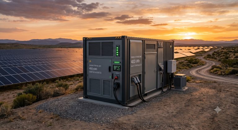
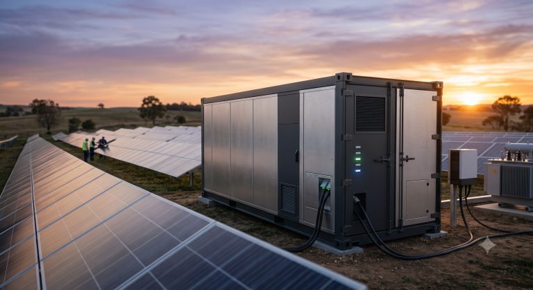
COMMERCIAL SYSTEMS ENGINEERING REFERENCE MANUAL: MEGAWATT ENERGY STORAGE ELECTRICAL SCHEMATICS
EXECUTIVE SUMMARY
This document serves as the definitive technical reference for the electrical architecture and schematics governing our Megawatt (MW) class Battery Energy Storage Systems (BESS). Designed for utility-scale and large Commercial & Industrial (C&I) applications, this platform integrates advanced power conversion, multi-level battery management, and grid-interactive controls into a cohesive, safety-certified system. The electrical schematics detailed herein represent a paradigm of efficiency, modularity, and resilience, ensuring seamless integration with renewable generation, grid infrastructure, and microgrid environments. Our approach prioritizes high round-trip efficiency, robust fault tolerance, and compliance with the most stringent international grid codes, establishing a new benchmark for scalable energy storage solutions.

SYSTEM ARCHITECTURE & SAFETY
The core of the MW-class BESS is built upon a modular, multi-tiered electrical topology designed for optimal performance and safety. The primary architecture features a high-voltage DC bus, which aggregates power from multiple battery racks in parallel. This DC bus interfaces with a bi-directional Power Conversion System (PCS) that handles the AC/DC conversion process, ensuring grid-synchronous power delivery. A dedicated Battery Management System (BMS) at the rack and module level provides granular monitoring and protection, while the Energy Management System (EMS) orchestrates the overall system logic and grid dispatch commands. Safety is ingrained at every level of the schematic design; key elements include integrated DC circuit breakers, fast-acting fuses, redundant contactors, and ground fault detection circuits, all coordinated to provide multiple layers of protection. The schematics are engineered to support both transformerless and transformer-coupled grid connections, depending on project-specific voltage and isolation requirements, offering unparalleled deployment flexibility.
KEY FEATURES
– HIGH-EFFICIENCY POWER CONVERSION: The schematics highlight a next-generation PCS topology that achieves up to 99.0% peak efficiency, significantly minimizing parasitic losses. This design features a three-level Neutral Point Clamped (NPC) topology for superior harmonic performance and lower filter losses, ensuring high-quality AC power that complies with IEEE 519 standards. A proprietary adaptive control algorithm dynamically adjusts switching frequencies to maintain optimal efficiency across varying load conditions, maximizing the system’s round-trip efficiency.
– MODULAR & SCALABLE BUS DESIGN: The DC busbar and interconnection schematics are designed for true modularity, enabling seamless expansion from a 1 MW baseline to multi-megawatt installations. Pre-configured busbar tap-off points and standardized interconnection cabinets allow for the straightforward addition of battery racks or PCS modules without significant redesign. This feature is critical for phased project deployments and offers a future-proof solution that adapts to growing energy demands.
– ADVANCED THERMAL & FAULT MANAGEMENT: The electrical schematics integrate a sophisticated thermal management interface that works in concert with the liquid cooling system. This interface provides dedicated power and control lines for coolant pumps and fans, with schematics engineered for N+1 redundancy to ensure operational integrity under extreme conditions. A comprehensive fault management scheme, incorporating instantaneous overcurrent protection and a multi-stage precharge circuit, protects the system from inrush currents and internal faults, guaranteeing a safe and reliable power flow path.
COMPLIANCE & STANDARDS
– UL 9540: Energy Storage Systems and Equipment
– UL 9540A: Test Method for Evaluating Thermal Runaway Fire Propagation
– IEC 62619: Secondary cells and batteries – Safety requirements
– IEC 62933: Electrical energy storage (EES) systems
– IEEE 1547: Standard for Interconnection and Interoperability of Distributed Energy Resources with Associated Electric Power Systems Interfaces
– NFPA 70: National Electrical Code (NEC)
TECHNICAL SPECIFICATIONS
| Parameter | Specification |
|---|---|
| DC Voltage Range | 600 VDC – 1500 VDC |
| Max. DC Current | 2,000 A (configurable) |
| Rated AC Power | 1,000 kW / 1,250 kVA |
| PCS Peak Efficiency | Up to 99.0% |
| Grid Frequency | 50/60 Hz |
| Primary Communication | CAN 2.0B, Modbus TCP/IP |
MEGAWATT ELECTRICAL SCHEMATIC PARAMETERS
DC SIDE SPECIFICATIONS
– Voltage Range: 600 VDC – 1500 VDC
– Max. DC Current: 2,000 A (configurable)
– Busbar Configuration: Copper, laminated, low-inductance design
– Short-Circuit Protection: High-speed DC-rated fuses and circuit breakers
AC SIDE SPECIFICATIONS
– Nominal AC Voltage: 380 VAC / 480 VAC / 690 VAC (field-selectable)
– Grid Frequency: 50/60 Hz
– Total Harmonic Distortion (THD): < 3% at rated load
- Power Factor: 0.9 leading to 0.9 lagging (adjustable)
PCS SPECIFICATIONS
- Rated AC Power: 1,000 kW / 1,250 kVA
- Peak Efficiency: Up to 99.0%
- Cooling Method: Forced air / Liquid-cooled (design-specific)
- Topology: Three-level NPC
CONTROL & PROTECTION INTERFACES
- Primary Control: CAN 2.0B, Modbus TCP/IP
- Protection Coordination: High-speed digital inputs for emergency stop (E-Stop), over-temperature, and over-current. Hardware interlock circuits for safety relay integration.
- Communication Protocol: IEC 61850, DNP3, Modbus
INDUSTRIAL DEPLOYMENT
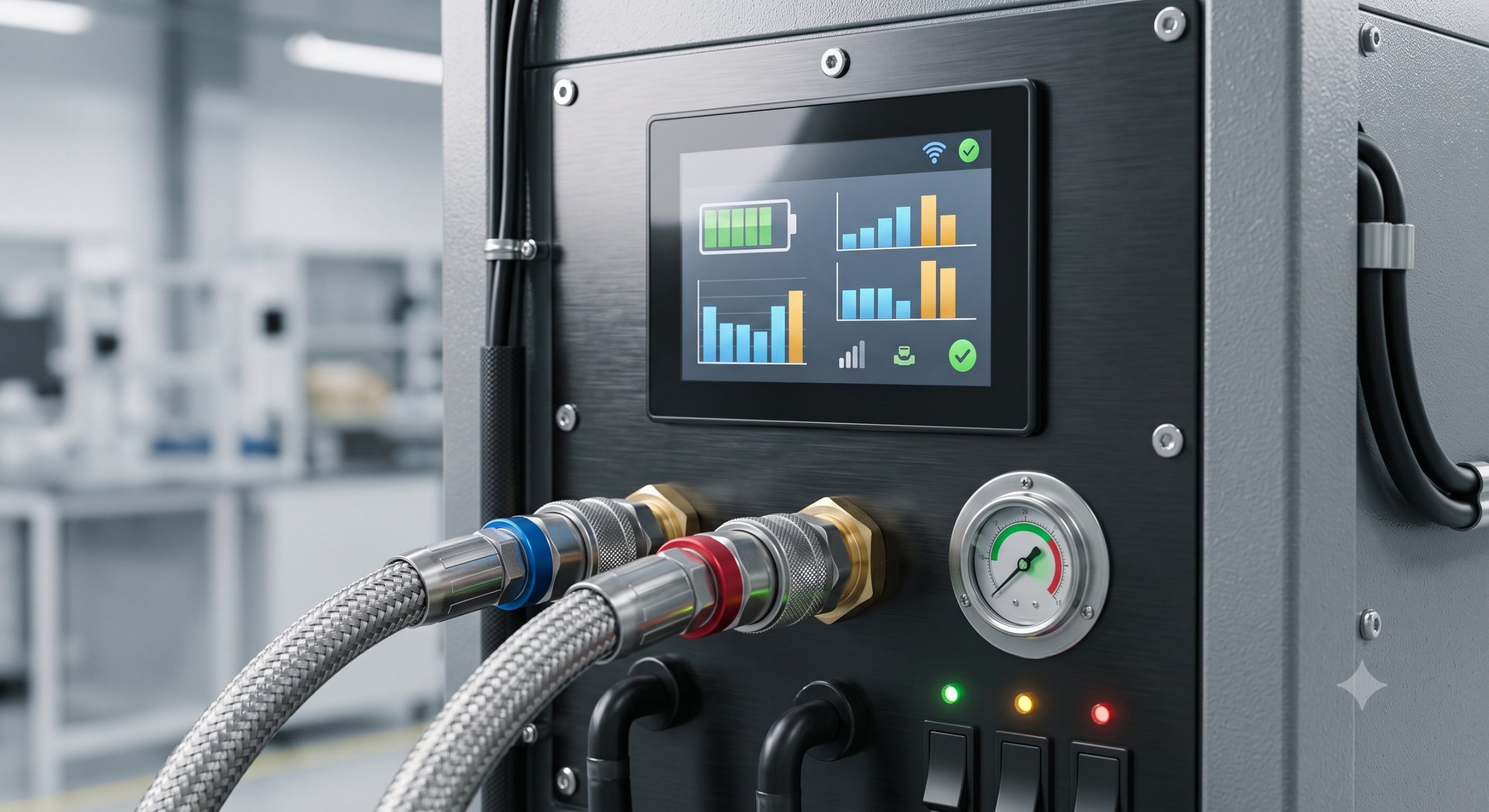
The electrical schematics are purpose-built for deployment across a wide spectrum of high-demand industrial applications, including peak shaving for manufacturing facilities, load leveling for large-scale data centers, and grid stabilization for renewable-heavy substations. The architecture’s adaptability is showcased in its support for both islanded (microgrid) and grid-connected modes, with a seamless transition capability of under 20 milliseconds for uninterruptible power supply (UPS) applications. The platform is designed for outdoor containerized or skid-mounted installations, featuring robust IP54 to IP65-rated enclosures that protect all electrical components from dust, moisture, and corrosive environments. A pre-engineered pad-mounted installation approach minimizes civil works and accelerates project timelines, ensuring a rapid return on investment.
📥 Download Technical Specification
Click the button below to view or download the full official PDF datasheet.